Clock and data recovery circuit

a clock and data technology, applied in the field of serial data communication, can solve the problems of consuming too much power and occupying too much space of flip-flops, and achieve the effect of reducing the number of d flip-flops

Inactive Publication Date: 2005-04-21
VIA TECH INC
View PDF8 Cites 20 Cited by
  • Summary
  • Abstract
  • Description
  • Claims
  • Application Information

AI Technical Summary

Benefits of technology

[0011] It is therefore a primary objective of the present invention to provide a CDR to reduce

Problems solved by technology

These D flip-flops not only occupy too mu

Method used


Image

  • Clock and data recovery circuit
  • Clock and data recovery circuit
  • Clock and data recovery circuit

Examples


Embodiment Construction

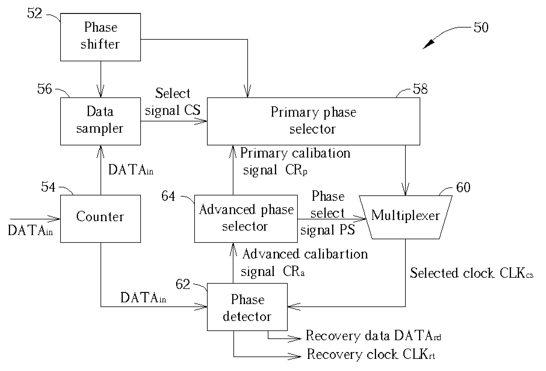
[0021] A phase shifter in a CDR according to the present invention generates M discrete clocks CLKdis wherein M is less than the number required by the prior art. At least one interpolated clock CLKint is then found from any two consecutive discrete clocks CLKdis by interpolation, and a set of clocks is formed by it and the two consecutive discrete clocks CLKdis. Subsequently, one clock CLKcs is selected being more synchronized to input data DATAin from the set of clocks. Since finding at least one interpolated clock CLKint by interpolation requires only one common circuit, a large number of D flip-flops as in the prior art are no longer required to implement the data sampler. So that the number of the D flip-flops, and accordingly the area occupied by the D flip-flops and the cost are effectively reduced.

[0022] Please refer to FIG. 4 showing a block diagram of a CDR 50 according to the present invention. The CDR 50 includes a phase shifter 52, a data sampler 56 electrically connec...


PUM


Abstract

A clock and data recovery circuit generates a recovery and a reference clock corresponding to the input data and includes a phase shifter generating M discrete clocks at different phases, a data sampler generating a select signal according to the input data and the M discrete clocks, a primary phase selector outputting two consecutive discrete clocks and at least one interpolated clock with a phase between the phases of the two consecutive discrete clocks, a multiplexer selecting one of the two consecutive discrete clocks or the interpolated clock as a selected output clock, a phase detector receiving the selected output clock as the recovery clock and outputting an advanced calibration signal if the recovery clock leads or lags the input data, an advanced phase selector receiving the advanced calibration signal and transmitting the phase select signal to the multiplexer for adjusting the selected output clock and a primary calibration signal.

Description

BACKGROUND OF INVENTION [0001] 1. Field of the Invention [0002] The present invention relates to serial data communications, and more specifically, to a clock and data recovery circuit (CDR) used in a serial data communication system. [0003] 2. Description of the Prior Art [0004] Compared with parallel data communications, serial data communications are small in size and have a longer transmission distances. Although slower than parallel data communications, recently developed serial data communication devices such as USB1.1 and USB2.0 have solved those disadvantages, wherein the transmission speed of USB1.1 is up to 12 Mbps, and USB2.0 up to 480 Mbps. [0005] Please refer to FIG. 1 showing a conventional serial data communication system. The serial data communication system 10 includes a transmitter 12 for transmitting data, a serial bus 14 connected to the transmitter 12 for transmitting data, and a receiver 16 for receiving data from the serial bus 14. Please refer to FIG. 2 showi...

Claims


Application Information

Patent Timeline
IPC IPC(8): H03L7/081H03L7/091H04L7/00H04L7/033
CPCH03L7/0814H04L7/0337H04L7/0025H03L7/091
Inventor WU, CHING-YEN
Owner VIA TECH INC
Why Eureka
Try Eureka