Control system for hydrostatic pump

a control system and hydrostatic pump technology, applied in the direction of pump control, pump parameter, positive displacement liquid engine, etc., can solve the problems of swashplate incorrect positioning, pump and servo system usually not matching the resolution and accuracy of input signal,

Inactive Publication Date: 2005-04-21
SAUER DANFOSS NORDBERG
View PDF17 Cites 18 Cited by
  • Summary
  • Abstract
  • Description
  • Claims
  • Application Information

AI Technical Summary

Benefits of technology

[0008] The present invention is a control system that controls the angle of a swashplate. The control system can be a microprocessor that receives information from a feedback sensor and setpoint sensor. The microprocessor determines not only the angle of the swashplate but also a set point command. From the information received from the se

Problems solved by technology

The pump and servo system usually do not match the resolution and accuracy of the input s

Method used


Image

  • Control system for hydrostatic pump
  • Control system for hydrostatic pump
  • Control system for hydrostatic pump

Examples


Embodiment Construction

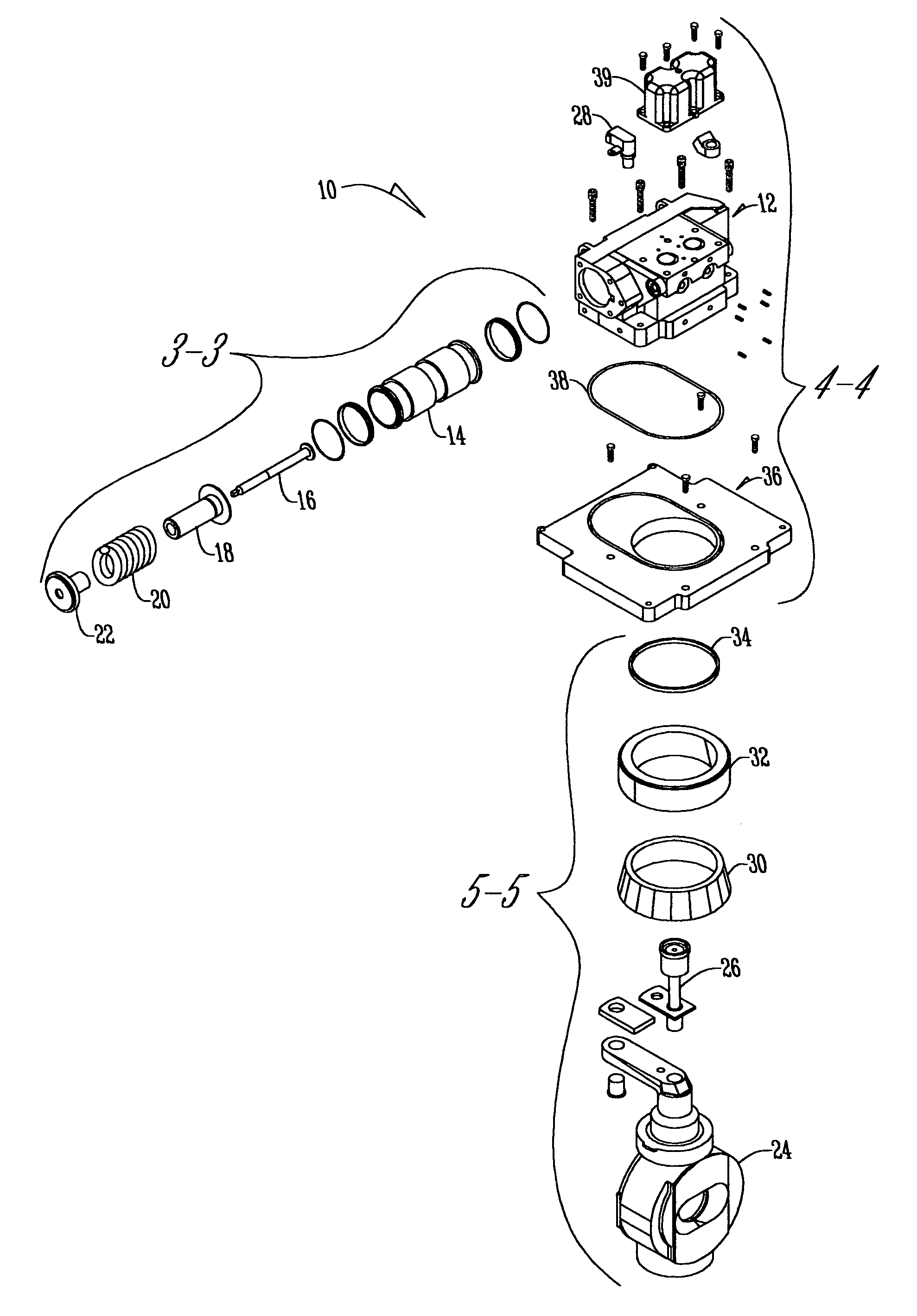
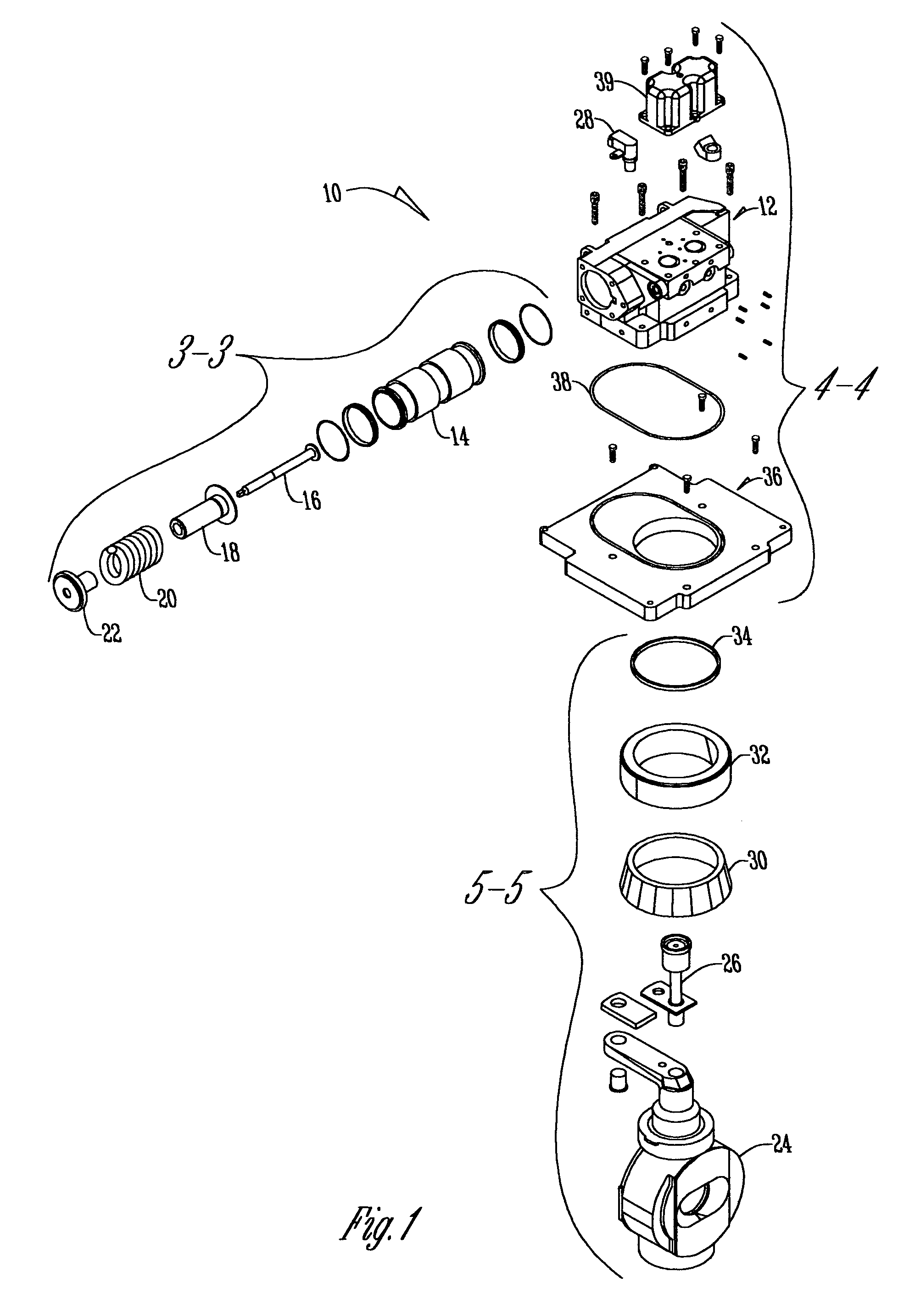
[0014] The control system of the present invention can be connected to the hydrostatic pump seen in FIG. 1. The hydrostatic pump 10 has a central housing 12 of a standard servo hydrostatic pump. A servo piston 14 is disposed through the central housing 12. The servo piston 14 incorporates a servo screw 16, spring guide 18, servo spring 20, and spring seat 22.

[0015] The hydrostatic pump 10 also has a swashplate 24. Swashplate 24 is connected to a shaft feedback assembly 26 that works with the angle sensor assembly 28 to determine the angle of the swashplate 24. The swashplate 24 connects to the central housing 12 by use of a cone bearing 30 that is connected to cup bearing 32 which is then connected to a first O-ring 34. The first O-ring 34 rests against the bottom of plate adapter 36. A second O-ring 38 meshes between the plate adapter 36 and the bottom of the central housing 12. On the top of the housing is a bi-directional pressure control PCP assembly 39 having two coils. As one...


PUM


Abstract

A control system that can be used on a hydrostatic pump has a feedback sensor to detect the angle of a swashplate. From the information gathered by the feedback sensor about the swashplate and another set command, this information is sent to a microprocessor. The microprocessor then uses an algorithm to create an output signal and also sends out a superimposed dither signal. This dithered output signal is then received by a pressure control that causes a dither servo pressure in a servo system. Because of the dither pressure the servo system adjusts the position of the swashplate.

Description

BACKGROUND OF THE INVENTION [0001] This invention relates to a control system for a hydrostatic unit. More specifically, and without limitation, this invention relates to a control system that utilizes a dither signal incorporated with its normal input signal in order to adjust the angle of a swashplate. [0002] In the art of hydraulics, oil is pumped by mechanical hydraulic pumps for the purpose of causing a hydraulic motor to revolve, a hydraulic cylinder extend, or for other useful purposes. A common aspect of many tractors, earthmoving machines, and the like is a hydrostatic transmission. In its most basic form a hydrostatic transmission consists of a hydrostatic pump which is normally driven by an internal combustion engine, and provides a source of pressurized oil flow which causes one or more hydrostatic motors to rotate. The rotation of these one or more hydrostatic motors will cause the machine to travel forward or reverse as commanded by the drive of the machine. [0003] The...

Claims


Application Information

Patent Timeline
IPC IPC(8): F04B1/26F04B1/32F04B49/06
CPCF04B1/324F04B2201/12051F04B49/065
Inventor KLOCKE, CRAIG C.
Owner SAUER DANFOSS NORDBERG
Why Eureka
Try Eureka