Freeze resistant buoy system

a buoy system and buoy technology, applied in special-purpose vessels, fire alarms, instruments, etc., can solve the problems of affecting the safety of personnel,

Inactive Publication Date: 2005-04-21
UT BATTELLE LLC
View PDF34 Cites 35 Cited by
  • Summary
  • Abstract
  • Description
  • Claims
  • Application Information

AI Technical Summary

Benefits of technology

[0007] Accordingly, objectives of the present invention include provision of buoy systems that are resistant to freezing, buoy systems that draw heat from deeper water to prevent freezing of the buoy systems, a

Problems solved by technology

Currently available buoy systems may be susceptible to freezing, disabling the activity of systems contai

Method used


Image

  • Freeze resistant buoy system
  • Freeze resistant buoy system
  • Freeze resistant buoy system

Examples


Embodiment Construction

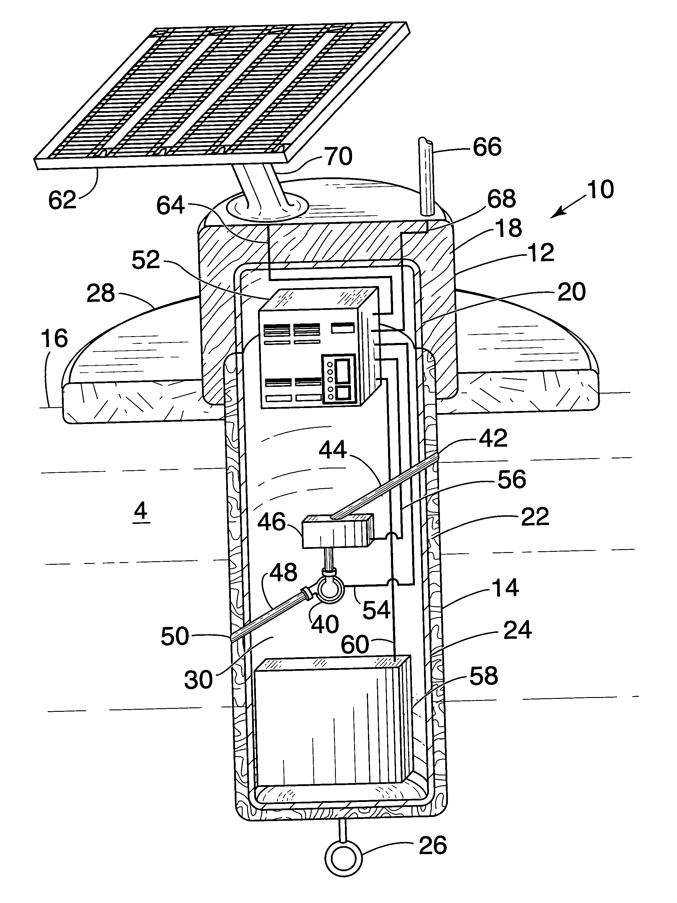
[0013] Referring to FIG. 1, the present invention is a tail-tube buoy system 200 that is adapted for deployment in colder climates. There are two essential parts to the buoy system 200, an upper section 220, which is disposed predominantly above the water line 216, and a lower section 202, which is disposed predominantly below the waterline 216. An anchoring ring 226 can be attached, for example to the bottom of the buoy 200. A buoyant stabilizing wing or collar 224 can be attached, for example, at the waterline 216.

[0014] The upper section 220 is comprised of a thermally insulating material 222, and, optionally, an inner liner 244 to provide structural integrity. The thermally insulating material 222 is preferably comprised of a suitable, commercially available insulation. Suggested examples are: blown foam; polystyrene foam; fiberglass; carbonaceous insulations such as Fiberform™ available from Fiber Materials, Inc., Selkirkshire, Scotland, UK; and carbon foam such as that availa...


PUM

PropertyMeasurementUnit
Timeaaaaaaaaaa
Electrical resistanceaaaaaaaaaa
Electrical conductoraaaaaaaaaa

Abstract

A freeze resistant buoy system includes a tail-tube buoy having a thermally insulated section disposed predominantly above a waterline, and a thermo-siphon disposed predominantly below the waterline.

Description

CROSS-REFERENCE TO RELATED APPLICATIONS [0001] Specifically referenced is commonly assigned U.S. Patent Application Serial No. ______ filed on even date herewith, entitled “Enhanced Monitor System for Water Protection”, the entire disclosure of which is incorporated herein by reference.[0002] The United States Government has rights in this invention pursuant to contract no. DE-AC05-00OR22725 between the United States Department of Energy and UT-Battelle, LLC.FIELD OF THE INVENTION [0003] The present invention relates to freeze resistant buoy systems, and more particularly to freeze resistant buoy systems that draw heat from deeper water to prevent freezing of the buoy systems. BACKGROUND OF THE INVENTION [0004] Currently available buoy systems may be susceptible to freezing, disabling the activity of systems contained therein. For example, recent terrorist attacks in the United States have increased the awareness of the need for ways to protect drinking water supplies. Source waters...

Claims


Application Information

Patent Timeline
IPC IPC(8): B63B22/24G01N21/00
CPCB63B2035/4453B63B22/24
Inventor HILL, DAVID E.RODRIQUEZ, MIGUEL JR.GREENBAUM, ELIASKLETT, JAMES W.
Owner UT BATTELLE LLC
Why Eureka
Try Eureka