Programmable controller, programmable controller system, CPU unit and method of starting duplexed operation

Active Publication Date: 2005-04-21
ORMON CORP
View PDF7 Cites 7 Cited by
  • Summary
  • Abstract
  • Description
  • Claims
  • Application Information

AI Technical Summary

Benefits of technology

[0024] It is preferable that the executing CPU unit be adapted to obtain unit version data of the standby CPU unit, compare the obtained unit version data with its own unit version data and to communicate the older unit version data to a support tool connected to the programmable controller and issue to the programmable controller a request for the unit version data. With the CPU units thus structured, the support tool is able to generate a user program according to the older unit version data and download it such that a duplexed operation can be carried out reliably by using such downloaded user program.

Problems solved by technology

Although the CPU unit of a standby system during a standby period carries out the same user program as that of the CPU unit of the executing system, it is not adapted to output the results of its calculations.
This may be done by downloading the user program to each of the CPU units but this is a troublesome way of implementation because the user will be required to carry out the same downloading process twice.
When the user program is copied from the CPU unit of the executing system to the CPU unit of the standby system, however, the support tool cannot check the version of the CPU unit.
In a situation where the CPU unit of the executing system is of the new version and the CPU unit of the standby system is of an old version, for example, the user program may be copied but as the copied user program is executed by the CPU unit of the standby system, it may stop the operation or carry out an abnormal operation if a circuit is encountered that cannot be handled by it.
The problem described above can be obviated if the form is changed whenever a new version is introduced such that CPUs of the same form will be used, but the number of forms will increase by this method and this will complicate the management of forms by the makers and users and hence is not a practical solution.

Method used


Image

  • Programmable controller, programmable controller system, CPU unit and method of starting duplexed operation
  • Programmable controller, programmable controller system, CPU unit and method of starting duplexed operation
  • Programmable controller, programmable controller system, CPU unit and method of starting duplexed operation

Examples


Embodiment Construction

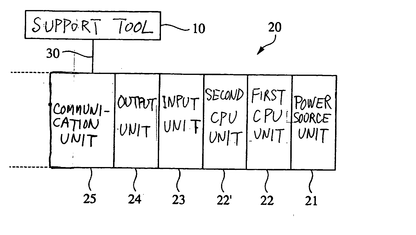
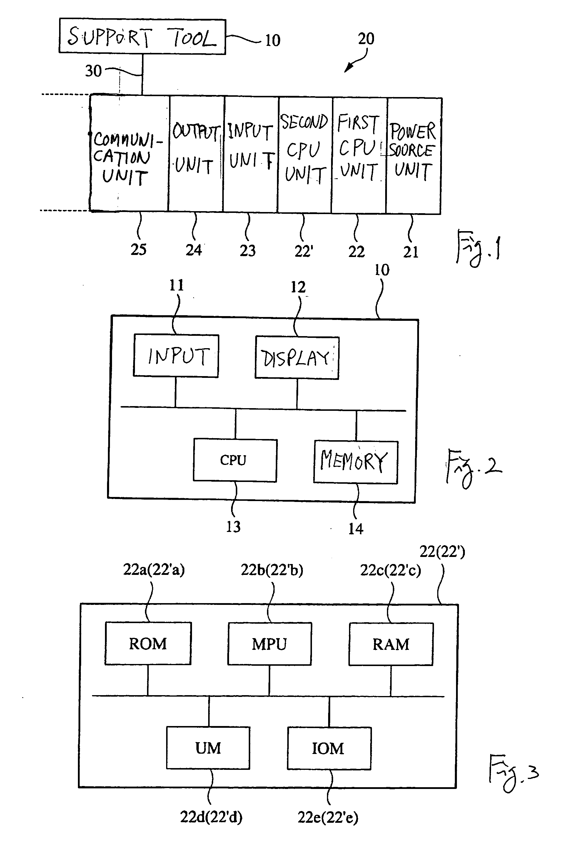
[0039]FIG. 1 shows a system embodying this invention, comprising a support tool 10 which may be embodied by a personal computer and a programmable controller PLC 20 connected through a network (communication line) 30. The network may be realized by a direct cable connection using a serial line such as RS232C, through which a user program created or amended by the support tool 10 may be downloaded to the PLC 20.

[0040] The PLC 20 is comprised of a plurality of units such as a power source unit 21 for supplying electrical power, first and second CPU units 22 and 22′ for controlling the PLC 20 as a whole, an input unit 23 for inputting signals from the switches and sensors placed at appropriate positions of a factory automation production equipments, an output unit 24 for outputting control outputs to actuators, etc. and a communication unit 25 connected to a communication network. User programs downloaded from the support tool 10 in the case of this system are stored and executed in t...


PUM


Abstract

A programmable controller has a first (executing) CPU unit and a second (standby) CPU unit for a duplexed operation. Each CPU unit stores CPU version indicating its functionality and function version indicative of the functionality of the user program stored in itself. Before the duplexed operation is started, the first CPU unit acquires the unit version of the second CPU unit, compares it with the function version stored in itself and judges from this comparison whether a duplexed operation is possible or not. Only if it is judged that the duplexed operation is possible, the first CPU unit copies the user program stored in itself to the second CPU unit together with the function version and the duplexed operation is started.

Description

[0001] Priority is claimed on Japanese Patent Applications 2003-335593 filed Sep. 26, 2003 and 2004-272617 filed Sep. 17, 2004. BACKGROUND OF THE INVENTION [0002] This invention relates to programmable controllers, systems using such programmable controllers, a CPU unit for such programmable controllers and methods of starting a duplexed operation of such a programmable controller system. [0003] Programmable controllers are being used as controlling devices for the factory automation set at a production factory (or a production site). Such a programmable controller (PLC) is comprised of a plurality of units, that is, it is formed by appropriately combining units of various types such as a power unit serving as a supply source of electric power, a CPU unit for carrying out the control of the PLC as a whole, an input unit for inputting signals from switches and sensors set at appropriate positions of a production device or an equipment of the factory automation, an output unit for tra...

Claims


Application Information

Patent Timeline
IPC IPC(8): G05B19/05G05B19/042G06F11/00G06F11/20
CPCG05B2219/24187G06F11/2038G06F11/004
Inventor OKEDA, HIDEONAGANO, EISUKENAKANISHI, EIJITOMITA, KENICHIRO
Owner ORMON CORP
Why Eureka
Try Eureka