

Slopped roof flashing system and method of use
a flashing system and roof technology, applied in roofs, snow traps, construction, etc., can solve the problems of sloping roof transitions, affecting the safety of workers, so as to save labor and material costs and protect from exposure
- Summary
- Abstract
- Description
- Claims
- Application Information
AI Technical Summary
Benefits of technology
Problems solved by technology
Method used
Image

Examples
Embodiment Construction
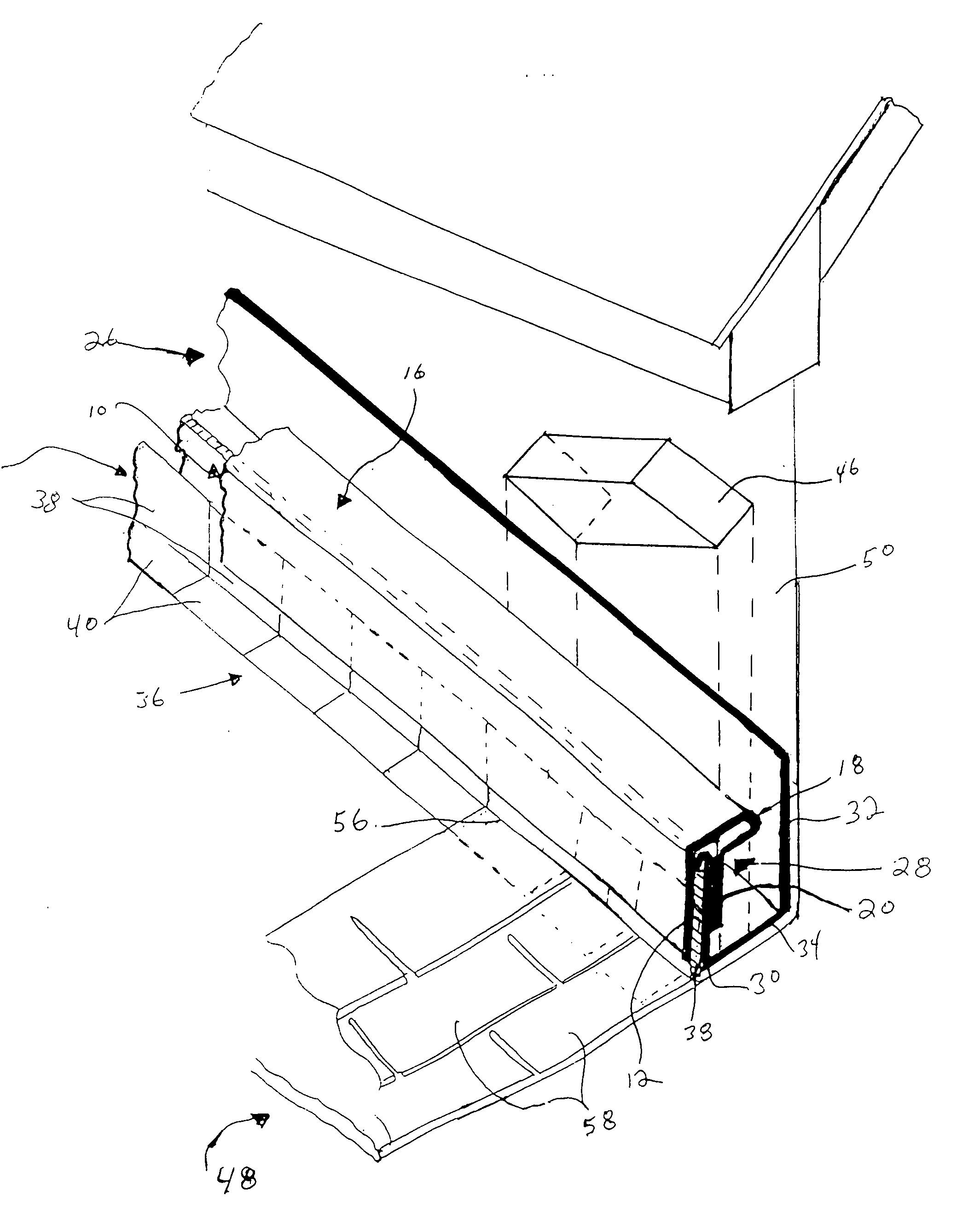
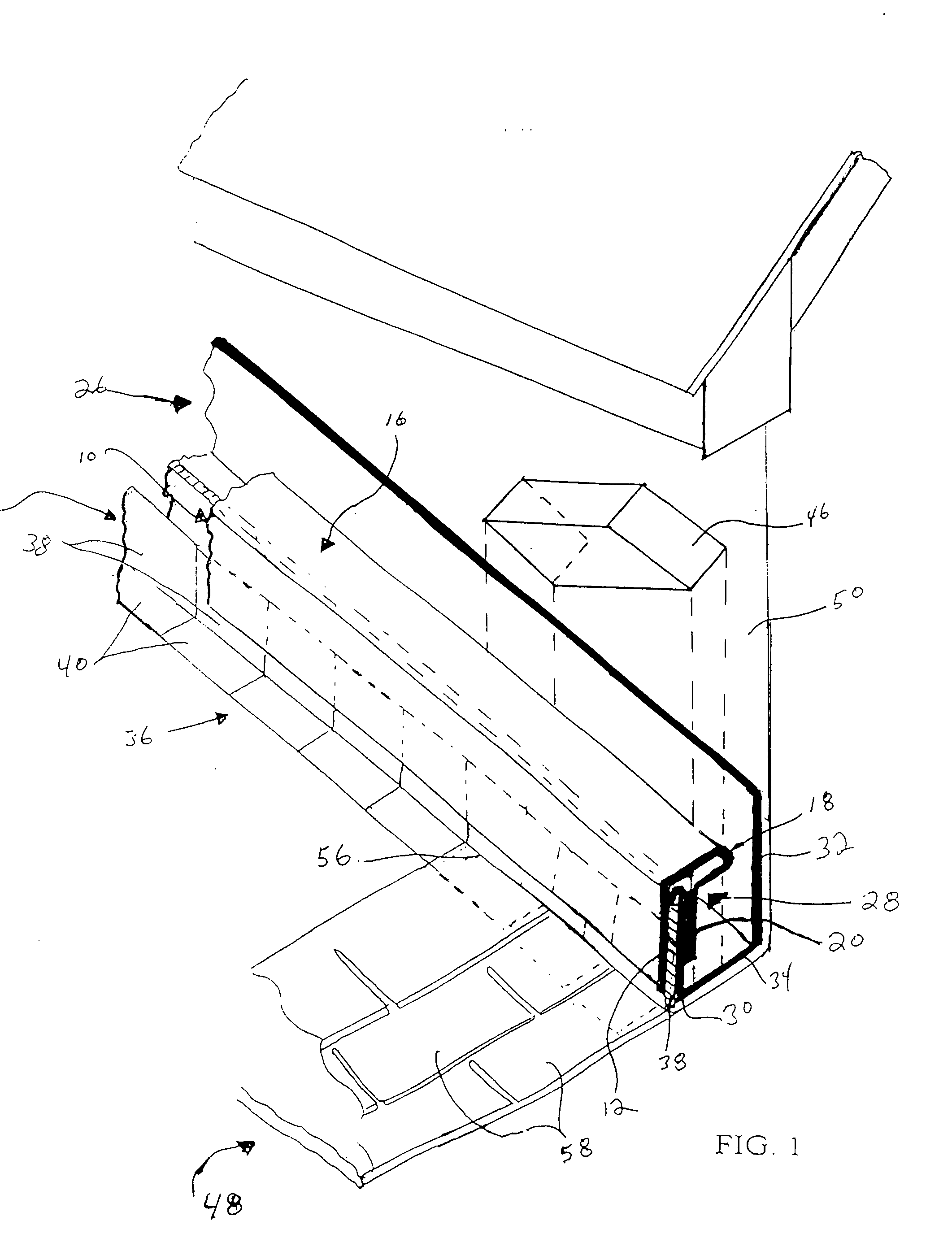
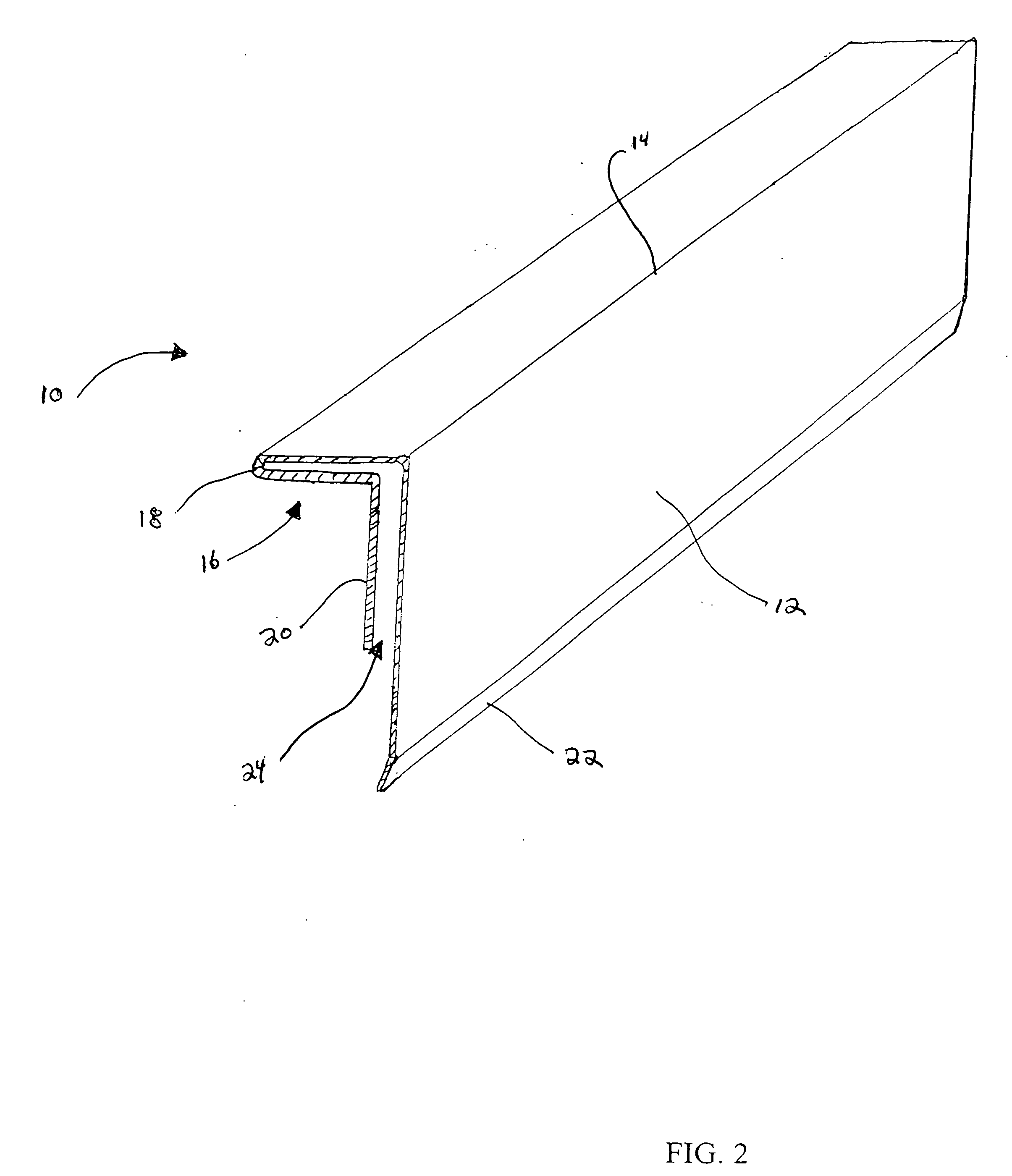
[0010] Referring to FIG. 2 and FIG. 3, the one-piece counter flashing 10 of the present invention has a flange 16 extending laterally from the top edge 14 of the apron 12. As shown, the flange 16 is turned downwardly upon itself in the manner of a hairpin to form a lip 18 from which a vertical planar section 20 extends downwardly in substantial parallel and spaced relationship to the apron 12 forming a slit 24. As shown in FIG. 4, the counter flashing 10 is adapted for interfitting with a J-Channel flashing 26 and L-shaped roof flashing 36a. Specifically, as shown in in FIG. 4, the vertical leaf section 38a of the L-shaped roof flashing 36a is positioned flush with the outer face of the low side 30 of the J-Channel flashing 26. Both low side 30 and vertical leaf section 38a are securely fitted in the slit 24 so that the apron 12 overlies the vertical leaf section 38a protecting the vertical leaf section 38a and low side 30 from exposure to rain water. Moreover, as shown in FIG. 4, t...
PUM
 Abstract
Description
Claims
Application Information