Snap-in grommet for a valve stem assembly

a technology of stem assembly and snap-in grommet, which is applied in the direction of mechanical equipment, transportation and packaging, and functional valve types, etc. it can solve the problems of tire valve assembly air leakage from the tire inflator hole, and affecting the service life of the tire valve assembly. , to achieve the effect of improving service life, reducing air leakage, and improving sealing

Active Publication Date: 2005-04-28
SENSATA TECHNOLOGIES INC
View PDF36 Cites 26 Cited by
  • Summary
  • Abstract
  • Description
  • Claims
  • Application Information

AI Technical Summary

Benefits of technology

[0009] The present invention generally provides an improved system (or apparatus) and an improved method for a tire pressure monitor (TPM) valve stem grommet. The present invention generally provides a snap-in grommet having an integral sleeve and at least one sealing interface (generally a plurality of sealing interfaces). Such an improved system and method for a valve stem grommet may provide improved sealing, reduced air leakage, and improved warranty when compared to conventional approaches.

Problems solved by technology

However, insertion of the valve stem into the tire pressure monitoring system through the outside of the wheel rim can lead to difficulties when trying to align the valve stem with the sensor housing of the tire pressure monitor.
Furthermore, abrasions are possible when tightening the valve stem assemblies due to the metal-to-rubber contact between the valve stem and the interior of the conventional tire inflator hole grommet and the outer surface of the grommet and the inflation hole.
Further still, electrolytic corrosion can occur since the valve stem and the wheel rim are typically implemented using dissimilar metals.
In addition, in conventional approaches to TPM systems, tire valve assembly air leakage from the tire inflator hole can occur.
However, air leakage can still occur from the tire inflator hole when such conventional approaches are utilized.
In particular, over-tightening of a valve stem retaining nut can crush and damage one or more sealing regions and cause air leakage.

Method used


Image

  • Snap-in grommet for a valve stem assembly
  • Snap-in grommet for a valve stem assembly
  • Snap-in grommet for a valve stem assembly

Examples


Embodiment Construction

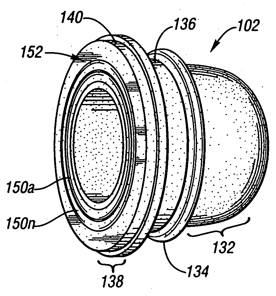
[0023] The present invention generally provides an improved system (or apparatus) and an improved method for a tire pressure monitor (TPM) valve stem grommet. The present invention generally provides a snap-in grommet having an integral sleeve and at least one sealing interface (and generally provides a plurality of sealing interfaces). Such an improved system and method for a valve stem grommet may provide improved sealing, reduced air leakage, and improved warranty when compared to conventional approaches.

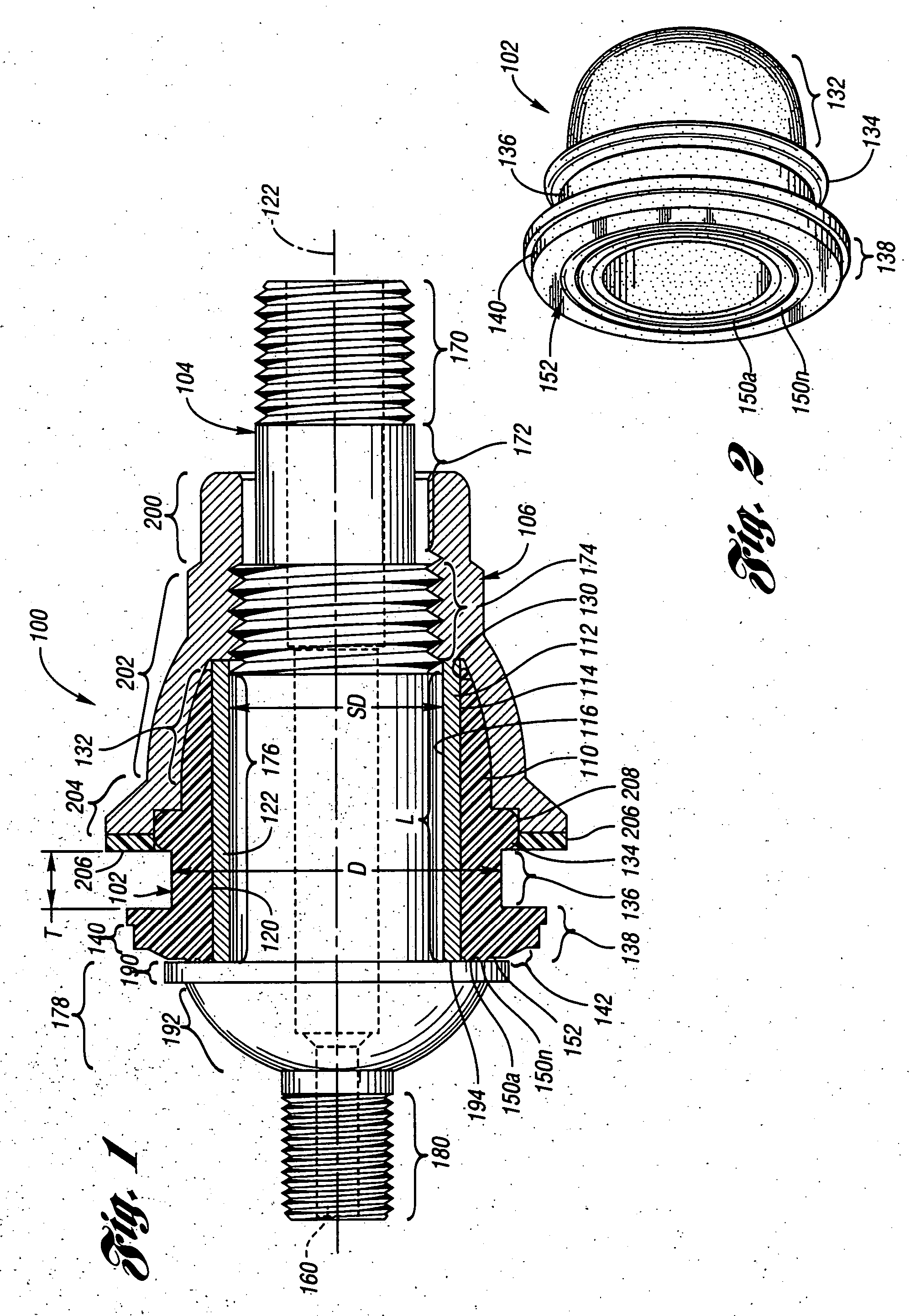
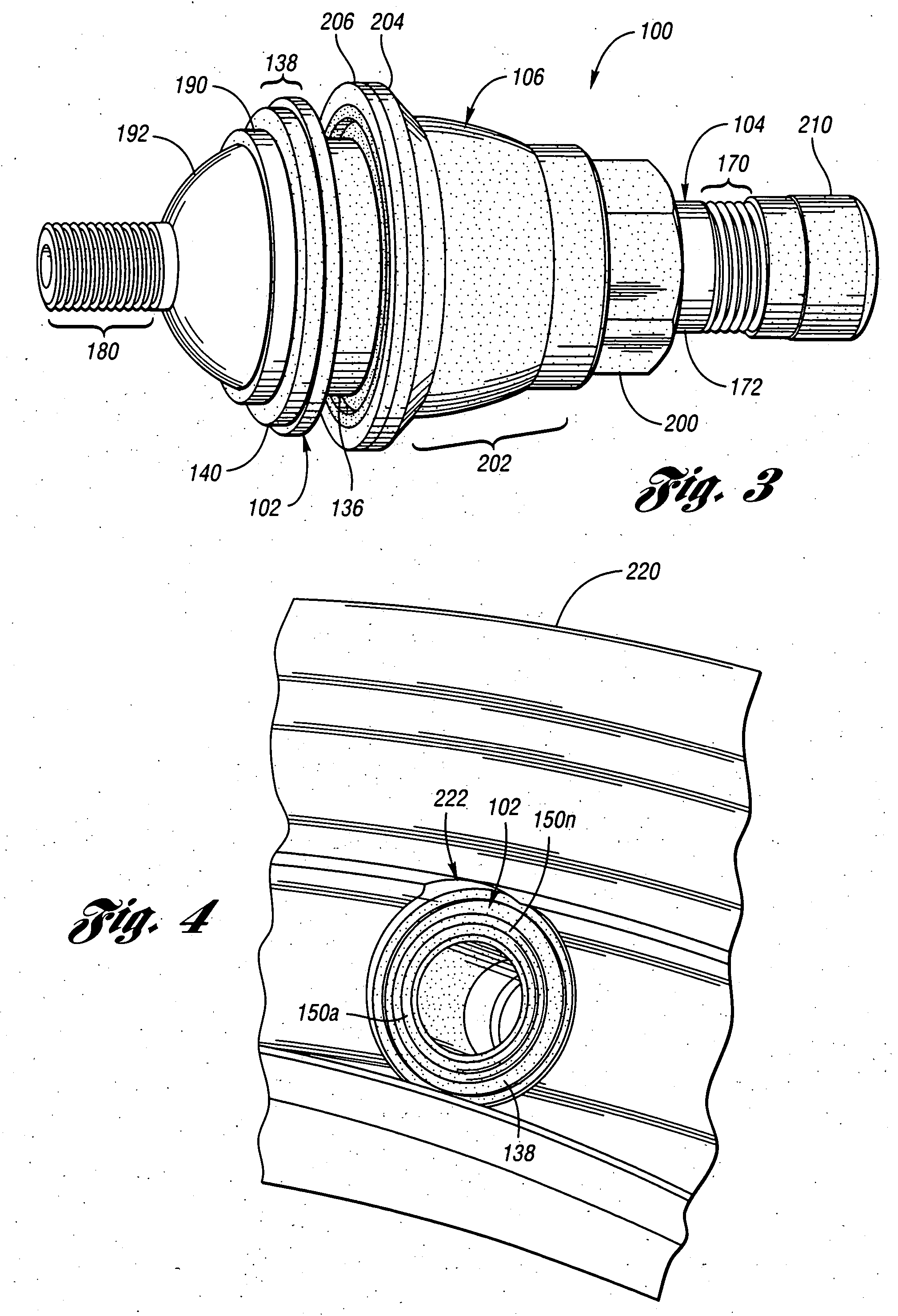
[0024] Referring to FIG. 1, a diagram illustrating a valve stem and grommet assembly 100 of the present invention is shown. The valve stem and grommet assembly 100 is generally implemented in connection with a vehicle wheel assembly TPM sensor and housing (described in more detail in connection with FIGS. 5 and 6). However, the assembly 100 may be implemented independently of a TPM system.

[0025] The assembly 100 generally comprises a grommet 102, a valve stem 104, and a retaini...


PUM


Abstract

The present invention includes a grommet and valve stem assembly. The assembly includes a grommet having a body, a nose section at a grommet first end, a cylindrical section having a first end adjoined to the nose section and a second end from which a flange section projects radially. The flange section has a substantially flat surface opposite to the cylindrical section. At least one interface seal is formed on the flat surface as a hemispherical projection located concentrically about a grommet center axis. An axial bore passes centrally through the body, and a valve stem is configured for insertion through the grommet bore. The valve stem includes a threaded portion configured to receive a retaining nut and a flange having a substantially flat surface configured to form at least one sealing interface with the at least one interface seal when the nut is tightened to the valve stem.

Description

BACKGROUND OF THE INVENTION [0001] 1. Field of the Invention [0002] The present invention relates to a snap-in grommet for a valve stem assembly tire pressure monitoring system. [0003] 2. Background Art [0004] Conventional tire pressure monitoring (TPM) systems for vehicles include a tire pressure sensor that is attached to a rim of a vehicle wheel assembly. In some TPM systems, the tire pressure sensor is contained in a sensor housing that includes an air pressure sensor. The sensor senses the air pressure in a tire of the wheel assembly and transmits a signal to a receiver outside the tire. The sensor housing contains a recess. A nut is positioned inside the recess and is threadably connected to a tire valve stem assembly. The valve stem extends through a tire inflator hole in the wheel rim. The sensor housing and nut provide alignment of the sensor, housing and valve stem. [0005] In other conventional TPM systems, the tire valve assembly is inserted through the outside of the whe...

Claims


Application Information

Patent Timeline
Patent Type & Authority Applications(United States)
IPC IPC(8): B60C23/04F16K15/20
CPCB60C23/0408F16K15/20B60C23/0494Y10T137/3584
Inventor ULESKI, MICHAEL A.
Owner SENSATA TECHNOLOGIES INC
Why Eureka
Try Eureka