Tire bead reinforcement comprising discontinuous reinforcing elements

a technology of discontinuous reinforcement and reinforcement elements, which is applied in the direction of tyre beads, yarn, transportation and packaging, etc., can solve the problems of certain distribution of discontinuous reinforcement ends and durrance problems that can aris

Inactive Publication Date: 2005-04-28
MICHELIN RECH & TECH SA
View PDF7 Cites 8 Cited by
  • Summary
  • Abstract
  • Description
  • Claims
  • Application Information

AI Technical Summary

Benefits of technology

[0024] This limit enables the cycles of stresses in the reinforcing elements of the said reinforcement to be reasonab

Problems solved by technology

When reinforcements are used which extend over an angular fraction smaller than 360° (such reinforcements being referred to as “discontinuous” in the present document), endurance prob

Method used


Image

  • Tire bead reinforcement comprising discontinuous reinforcing elements
  • Tire bead reinforcement comprising discontinuous reinforcing elements
  • Tire bead reinforcement comprising discontinuous reinforcing elements

Examples


Embodiment Construction

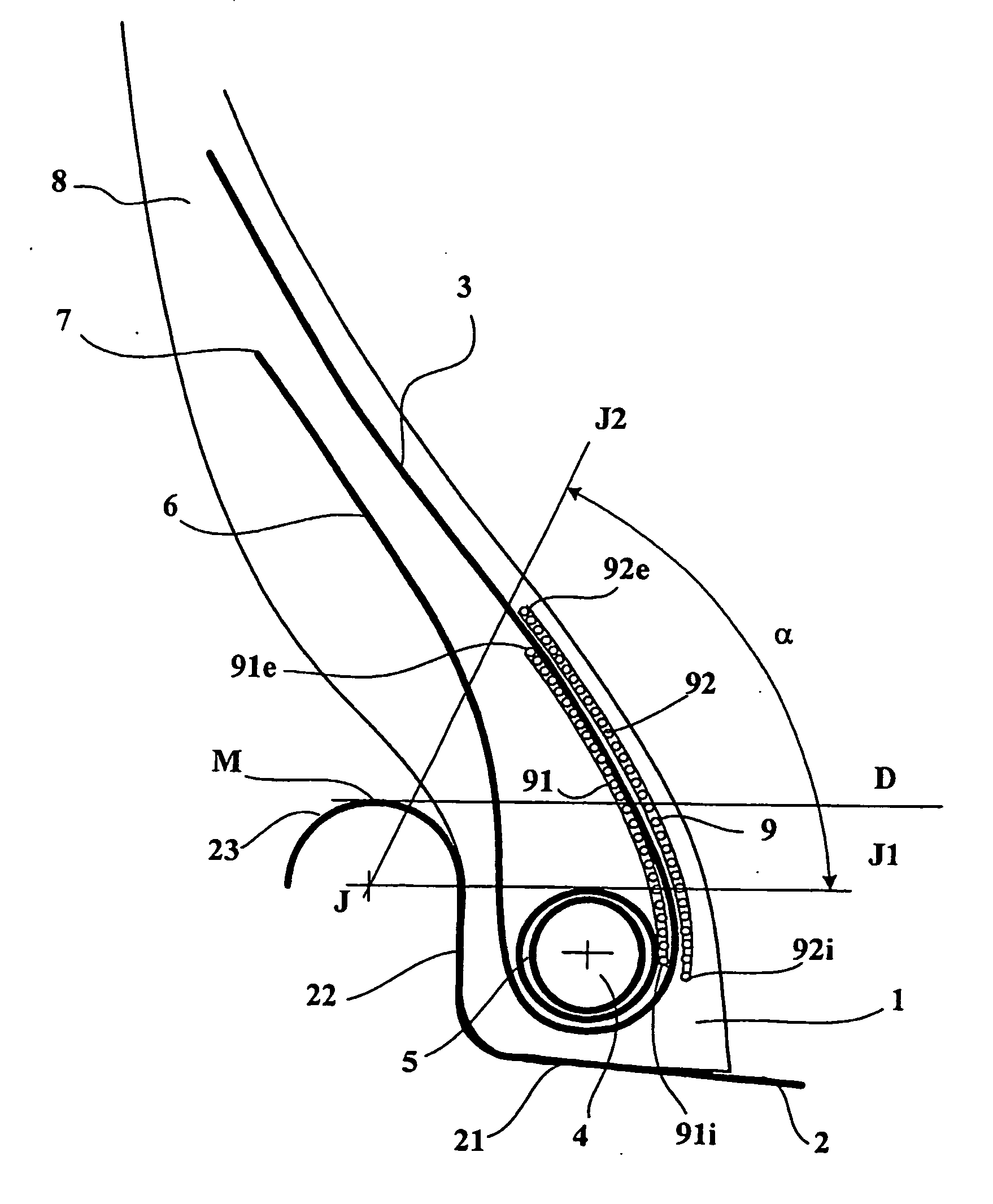
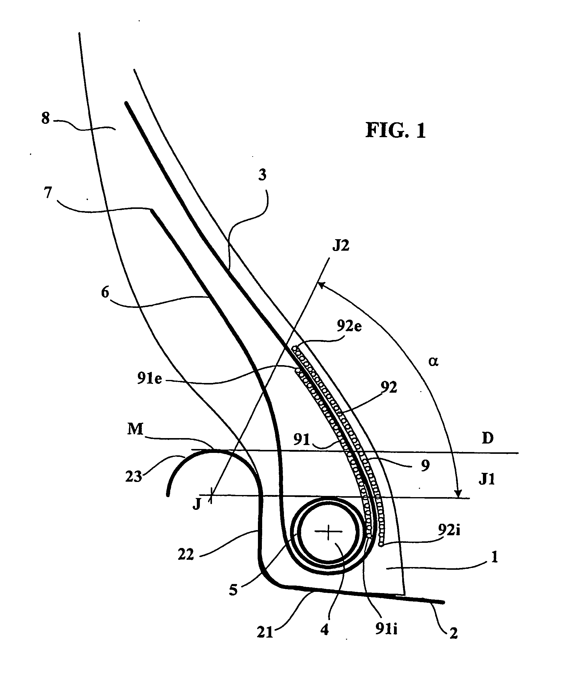
[0043] A tire of size 45 / 65 R 45 was produced and is shown in FIG. 1 mounted on a rim 2, viewed in partial cross-section. In FIG. 1 the mounting rim 2 comprises a portion forming a seat 21 extended axially and radially outwards by a flange 22 perpendicular to the rotation axis, this flange 22 ending in a part forming a rim hook 23 whose profile is substantially circular with its centre at J. FIG. 1 also shows a sidewall 8 extended by a bead 1 of the tire according to the invention mounted on a mounting rim 2 and inflated to its working pressure. The tire comprises a carcass reinforcement 3 reinforced by metallic cables formed of 68 hooped 0.26 mm wires, this carcass reinforcement 3 being turned up within each bead around a circumferential bead reinforcement 4; in the present case, the circumferential bead reinforcement is a metallic bead wire 4 provided all round with a thickness of rubber mix 5 designed to avoid direct contact between the reinforcing elements of the carcass reinfor...


PUM

PropertyMeasurementUnit
Angleaaaaaaaaaa
Angleaaaaaaaaaa
Angleaaaaaaaaaa

Abstract

A tire for vehicles carrying heavy loads, comprising in at least one bead an additional reinforcement composed of a plurality of discontinuous reinforcing elements, these discontinuous reinforcing elements being orientated essentially circumferentially to form a plurality of circles C, C1, C2 concentric on the rotation axis of the tire mounted on its rim, each circle being defined by a mean radius (R, R1, R2) measured relative to the said rotation axis, and wherein
    • [0001]
    • each discontinuous reinforcing element of length L0 located on a circle C of radius R is mechanically coupled over coupling lengths L11 and L12 with two discontinuous reinforcing elements located on a circle C1 of radius R1, this circle being immediately adjacent to the circle C, the coupling length L11 being between 55 and 75% of L0 and the coupling length L12 being between 10 and 30% of L0;
    • [0002]
    • each discontinuous reinforcing element on the same circle C of radius R is mechanically coupled over coupling lengths L21 and L22 with two discontinuous reinforcing elements located on a circle C2 of radius R2 immediately adjacent to the circle C1, the coupling length L21 being between 20 and 40% of L0 and the coupling length L22 being between 45 and 65% of L0.

Description

FIELD OF INVENTION [0003] The invention concerns a tire with radial carcass reinforcement intended for fitting on vehicles carrying heavy loads and more particularly construction machinery or heavy vehicles. BACKGROUND OF INVENTION [0004] A tire with radial carcass reinforcement comprises a crown zone surmounted radially on the outside by a tread designed to come in contact with the ground during the rolling of the said tire, with two sidewalls which extend the crown axially and radially on either side and which end in zones forming tire beads. The tire is then fitted on a mounting rim comprising rim seats of frustoconical or cylindrical shape which may or may not be extended by flanges, depending on the type of tire, these seats or flanges when present being extended by rim hooks of substantially circular shape. [0005] The beads of the said tire come in contact with the seats and hooks of this mounting rim. The carcass reinforcement of the tire consists of a plurality of reinforcin...

Claims


Application Information

Patent Timeline
IPC IPC(8): B60C1/00B60C15/06
CPCB60C15/06Y10T152/10819Y10T152/10828B60C15/00B60C15/04
Inventor DURIF, PIERRESALLAZ, GILLESGERVAIS, PHILIPPE
Owner MICHELIN RECH & TECH SA
Why Eureka
Try Eureka