
Electrochemical display element and electrochemical display

a technology of electrochemical display and display element, which is applied in the direction of electrolysis components, electrolytic organic production, instruments, etc., can solve the problems of inability to use reading for several hours or longer, inability to read information at the place in which a computer is located, and long time reading difficulties

Inactive Publication Date: 2005-04-28
SONY CORP
View PDF1 Cites 9 Cited by
  • Summary
  • Abstract
  • Description
  • Claims
  • Application Information

AI Technical Summary

Benefits of technology

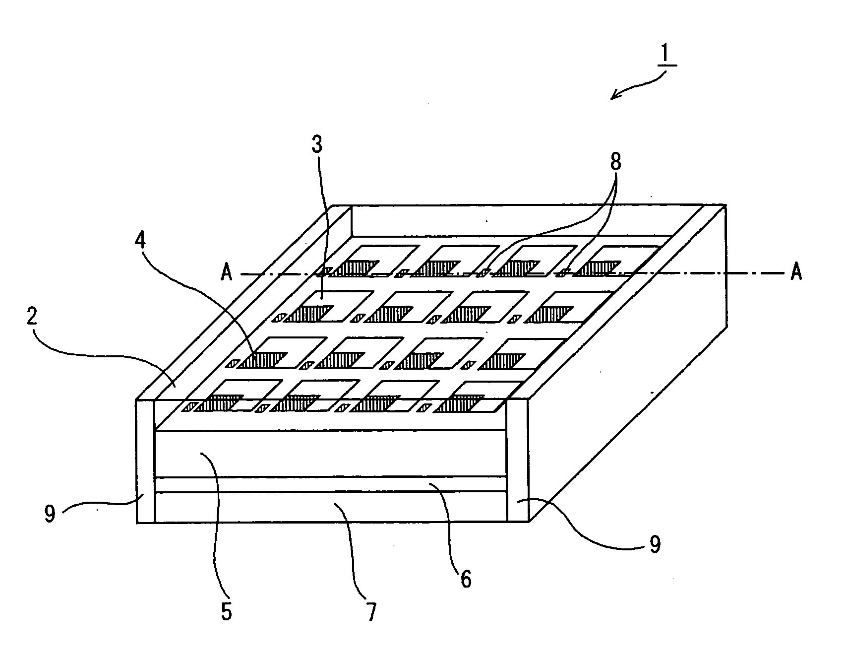
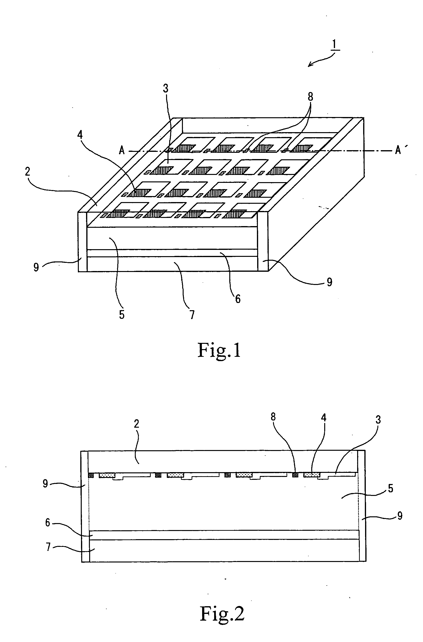
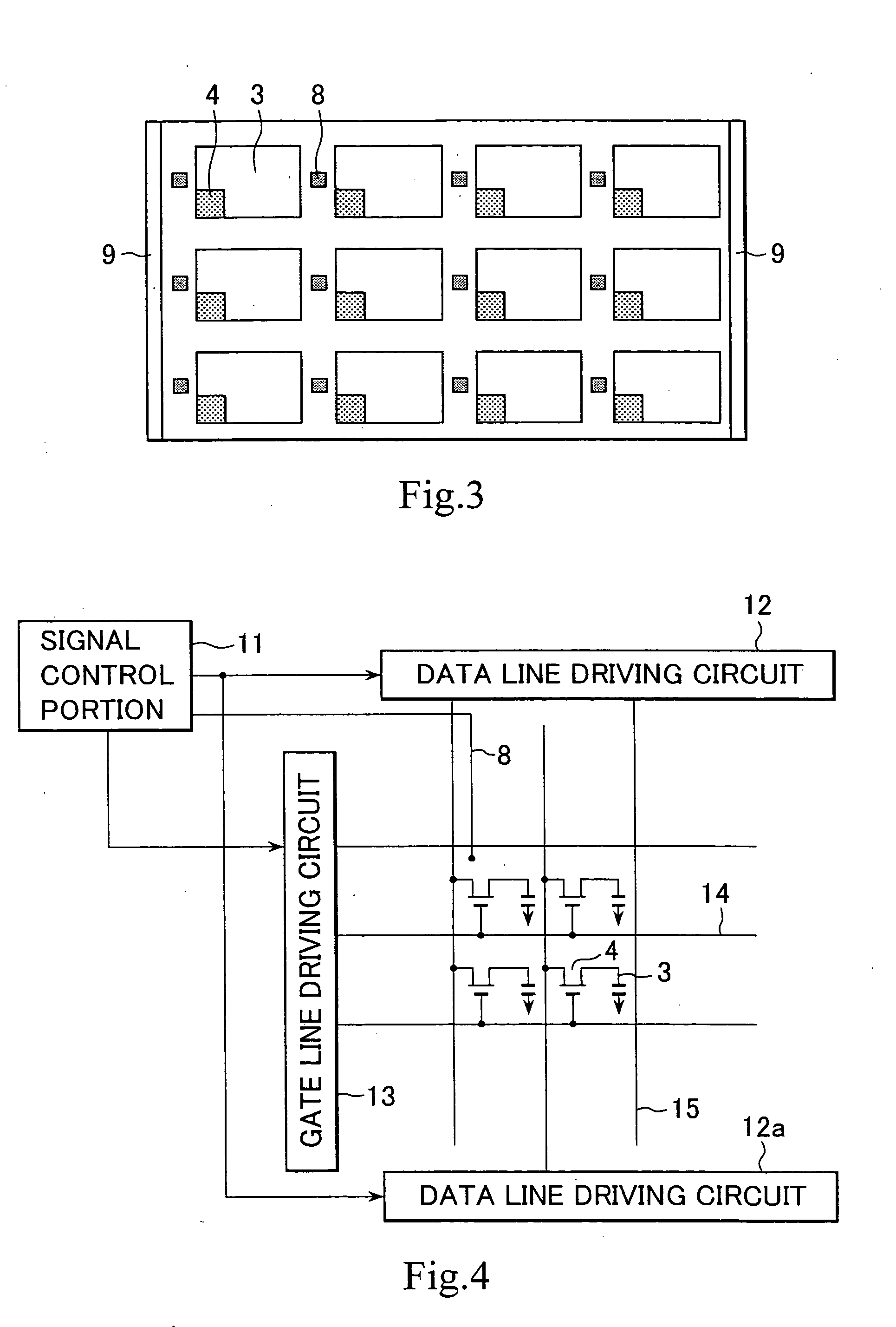
[0011] In the electrochemical display device according to the present invention having the above configuration, by virtue of having the third electrode independent of the first transparent electrode and the second electrode, the reaction state during the deposition or dissolution of the coloring material is precisely detected without being affected by the first transparent electrode and second electrode. Therefore, a point in time when the deposition or electrochemical reaction satisfactorily proceeds at the electrode is precisely detected, and driving is controlled based on the result of detection, achieving precise control of the driving. In addition, the precise control of the driving prevents the reaction from proceeding to an excess extent, so that the occurrence of a side reaction due to the excess reaction is prevented.
[0013] In the electrochemical display apparatus according to the present invention having the above configuration, the electrochemical display device constituting the electrochemical display apparatus has the third electrode independent of the first transparent electrode and the second electrode, and hence the reaction state during the deposition or dissolution of the coloring material is precisely detected without being affected by the first transparent electrode and second electrode. Therefore, a point in time when the deposition or electrochemical reaction satisfactorily proceeds at the electrode is precisely detected, and driving is controlled based on the result of detection, achieving precise control of the driving. In addition, the precise control of the driving prevents the reaction from proceeding to an excess extent, so that the occurrence of a side reaction due to the excess reaction is prevented.
[0015] In the above method for producing an electrochemical display device according to the present invention, the third electrode independent of the first transparent electrode and the second electrode is formed, and therefore a device is produced in which the reaction state during the deposition or dissolution of the coloring material is precisely detected without being affected by the first transparent electrode and second electrode. Thus, there is produced an electrochemical display device advantageous in that driving is precisely controlled to prevent the occurrence of a side reaction due to the excess reaction.
[0017] In the above method for producing an electrochemical display apparatus according to the present invention, the third electrode independent of the first transparent electrode and the second electrode is formed when forming an electrochemical display device, and therefore a display apparatus is produced in which the reaction state during the deposition or dissolution of the coloring material is precisely detected without being affected by the first transparent electrode and second electrode. Thus, there is produced an electrochemical display apparatus advantageous in that driving is precisely controlled to prevent the occurrence of a side reaction due to the excess reaction.

Problems solved by technology

However, it is pointed out that a light emission type display causes severe fatigue for the reasons of ergonomics, making long-time reading difficult.
In addition, there is a drawback in that information can be read only at the place in which a computer is located.
Laptop computers widely spread currently, and some of them are used as portable display, but they cannot be used in reading for several hours or longer because they are of a light emission type using a back light and further consume the power soon.
Recently, a reflection type liquid crystal display is developed, and the use of this enables driving of a computer with low power consumption; however, the liquid crystal has only a reflectance of plain display (white display) as low as 30%, and hence has markedly poor visibility, as compared to printed paper, and is likely to cause fatigue, thus also making long-time reading difficult.
However, these methods have disadvantages in that spaces between the particles absorb a light to lower the contrast, and the driving voltage required for obtaining a practical writing speed (1 second or faster) is as high as 100 V or more.
However, the photochromic glass and clock display essentially have no need of matrix driving, and hence cannot be applied to display use of electronic paper, and they generally have poor black quality and low reflectance.
However, an organic material generally has poor light resistance and hence poses a problem in that black color is faded and the black density is lowered after being used for a long time.
However, the properties, especially cycle properties are unsatisfactory, and it is desired that the cycle properties are improved.
In addition, there is a problem in that appropriate control of the oxidation reduction reactions is not satisfactorily achieved and the image remains upon display switching, that is, afterimage is caused, thus lowering the image quality.

Method used


Image

  • Electrochemical display element and electrochemical display
  • Electrochemical display element and electrochemical display
  • Electrochemical display element and electrochemical display

Examples


first embodiment

[0188] The first embodiment is an example of the arrangement in which a third electrode 59 in a line form is arranged on the transparent picture element electrode substrate so as to surround the whole of the effective picture elements on the side of the transparent picture element electrodes 52 as shown in FIG. 21. The third electrode 59 is connected to third electrode withdrawal portions 60, 61, 62, 63. As shown in FIG. 22, on the transparent picture element electrodes 52, insulating layers 58 are formed so as to be perpendicular to the transparent picture element electrodes 52. At the portion on which the third electrode 59 is disposed, as shown in FIG. 23, the third electrode 59 is formed on the insulating layer 58. When the third electrode is arranged so as to surround the whole of the effective picture elements as described above, the opening ratio can be increased, making it possible to constitute an electrodeposition type display device having preferable light withdrawal effi...

second embodiment

[0189] The second embodiment is an example of the arrangement in which top and bottom third electrodes 59 in a line form are arranged, on the transparent picture element electrode substrate, in the direction parallel to the stripe structure of the transparent picture element electrodes 52 so that the whole of the effective picture elements are disposed between the two third electrodes as shown in FIG. 24. The top and bottom third electrodes 59 are connected, respectively, to third electrode withdrawal portions 60, 61 and third electrode withdrawal portions 62, 63. As shown in FIG. 25, on the transparent picture element electrodes 52, insulating layers 58 are formed so as to be perpendicular to the transparent picture element electrodes 52. When the top and bottom third electrodes are arranged so that the whole of the effective picture elements are disposed between the two third electrodes as described above, the opening ratio can be increased, making it possible to constitute an ele...

third embodiment

[0190] The third embodiment is an example of the arrangement in which right and left third electrodes 59 in a line form are arranged, on the transparent picture element electrode substrate, in the direction perpendicular to the stripe structure of the transparent picture element electrodes 52 so that the whole of the effective picture elements are disposed between the right and left third electrodes as shown in FIG. 26. The right and left third electrodes 59 are connected, respectively, to third electrode withdrawal portions 60, 63 and third electrode withdrawal portions 61, 62. As shown in FIG. 27, on the transparent picture element electrodes 52, insulating layers 58 are formed so as to be perpendicular to the transparent picture element electrodes 52. At the portion on which the third electrode 59 is disposed, as shown in FIG. 28, the third electrode 59 is formed on the insulating layer 58. When the two third electrodes are arranged so that the whole of the effective picture elem...


PUM

PropertyMeasurementUnit
reflectanceaaaaaaaaaa
thicknessaaaaaaaaaa
thicknessaaaaaaaaaa

Abstract

An electrochemical display device and an electrochemical display apparatus, having preferable cycle properties and preferable display quality, and a method for producing the same. The electrochemical display device according to the present invention is characterized in that it has: a first transparent electrode; an electrolyte layer containing a coloring material which colors by a coloring means and electrochemical reduction or oxidation, accompanied by deposition or dissolution; a second electrode having the electrolyte layer disposed between the first transparent electrode and the second electrode; and a third electrode independent of the first transparent electrode and the second electrode.

Description

TECHNICAL FIELD [0001] The present invention relates to an electrochemical display device using a principle such that the color of a material is changed utilizing electrochemical oxidation or reduction. BACKGROUND ART [0002] In recent years, as the network widely spreads, documents, which have conventionally been delivered in the form of prints, are being delivered in the form of so-called electronic documents. Further, books, magazines and the like are frequently provided through so-called electronic publication. [0003] The information has been read conventionally from a CRT or liquid crystal display of a computer. However, it is pointed out that a light emission type display causes severe fatigue for the reasons of ergonomics, making long-time reading difficult. In addition, there is a drawback in that information can be read only at the place in which a computer is located. [0004] Laptop computers widely spread currently, and some of them are used as portable display, but they ca...

Claims


Application Information

Patent Timeline
Patent Type & Authority Applications(United States)
IPC IPC(8): C25B1/00C25B3/00C25C1/00C25C3/00G02F1/1506G02F1/155
CPCG02F1/1506G02F2001/1635G02F1/155
Inventor TAKAHASHI, KENICHI
Owner SONY CORP
Learn More