Scanning system and calibration method for capturing precise three-dimensional information of objects

a three-dimensional information and calibration method technology, applied in the field of scanning systems, can solve the problems of reducing treatment time, requiring a large amount of time and labor, and requiring a large amount of adaptations and corrections, so as to reduce the amount of equipment and reduce the amount of processing time

Inactive Publication Date: 2005-04-28
ORAMETRIX
View PDF19 Cites 99 Cited by
  • Summary
  • Abstract
  • Description
  • Claims
  • Application Information

AI Technical Summary

Benefits of technology

[0032] The scanning system enables three-dimensional surface information to be obtained with a very high decree of precision. Moreover, the scanning system can be used without requiring precise movement of the scanner, or requiring the object under scrutiny to be fixed in space. Surprisingly, the scanner is able to generate precise three dimensional surface information by simply moving the scanner over the surface of the object, such as by hand, in any manner that is convenient for the user, even if the object moves in any random direction during the scanning within reasonable limits. Thus, the scanner can be used to capture the surface of a patient's dentition in a minute or two, even if the patient moves their head or jaw while the scanning is occurring. Precise knowledge of the spatial relationship between the scanner and the object is not required.
[0061] The memory storing the calibration relationship (e.g., table) can be in the scanner itself or in a workstation for the scanner. Multiple calibration relationships for multiple scanners can be stored in a general-purpose computer (e.g., scanner workstation) used for the calculation of the 3-D values. When images are generated by the scanner and written to a memory, a code is included indicating the serial number of the scanner that generated the images. The computer retrieves the proper calibration relationship for the scanner per the code or serial number. In this way, the computer (e.g., scanning work station) can perform the required calculations of surface geometry without regard to which specific scanning device is used to capture the images of the object, such as in the case where one of the scanners is being used elsewhere and a new one is used, the regular scanner is out for repair and a new scanner is obtained, multiple scanners are shared in the same office, etc.

Problems solved by technology

However, it is obvious that such an approach requires an extreme amount of time and labor, and this is the reason why it is not widely used.
While at the beginning of treatment things generally run well as all teeth start to move at least into the right direction, at the end of treatment a lot of time is lost by adaptations and corrections required due to the fact that the end result has not been properly planned at any point of time.
And the patient has no choice and does not know that treatment time could be significantly reduced if proper planning was done.
As noted in the Massen et al. patent, the Brandestini et al. technique is difficult to use when there are large variations in surface topography since such large jumps displace the pattern by an amount larger than the phase constant of the pattern, making it difficult to reconstruct the pattern of lines.
Furthermore, the scanner has to be rather carefully positioned with respect to the tooth and would be unable to make a complete model of the dentition.
The system of the '281 patent is not particularly flexible, since it requires the object to be placed on the rotational stage and precise control of the relative position of the object and the positioning head is required at all times. It is unsuited for in vivo scanning of the teeth.
Moreover, the video technique does not produce complete three-dimensional information as to the teeth, but rather a limited amount of two-dimensional information, requiring significant manual operator input.

Method used


Image

  • Scanning system and calibration method for capturing precise three-dimensional information of objects
  • Scanning system and calibration method for capturing precise three-dimensional information of objects
  • Scanning system and calibration method for capturing precise three-dimensional information of objects

Examples


Embodiment Construction

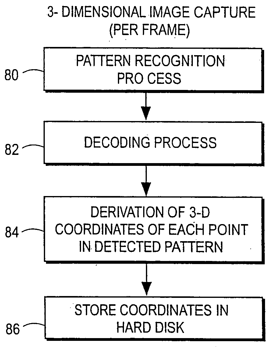
30Part 1 Overview30Part 2 Three Dimensional Image Generation40Scanner Manufacture and Calibration43Pattern Recognition57Decoding59Derivation of 3-D Point Cloud Per Image64Part 3 Generation of Digital Impression71Entry point into registration71Frame to frame registration72Cumulative registration81Segment registration87Landmarking88Separation of teeth into individual tooth objects91Part 4 Introduction to Treatment Planning105Other Uses of Scanner108Claims111

BACKGROUND OF THE INVENTION

[0018] A. Field of the Invention

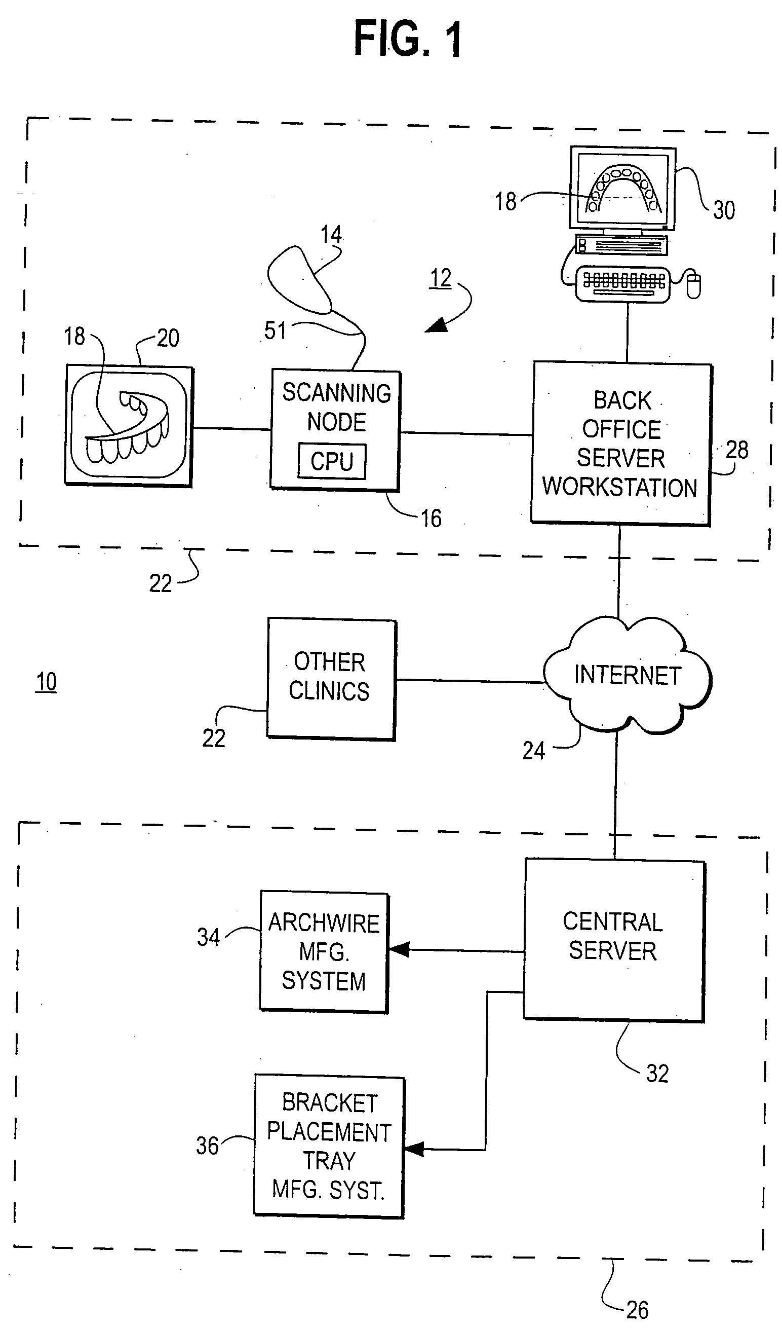
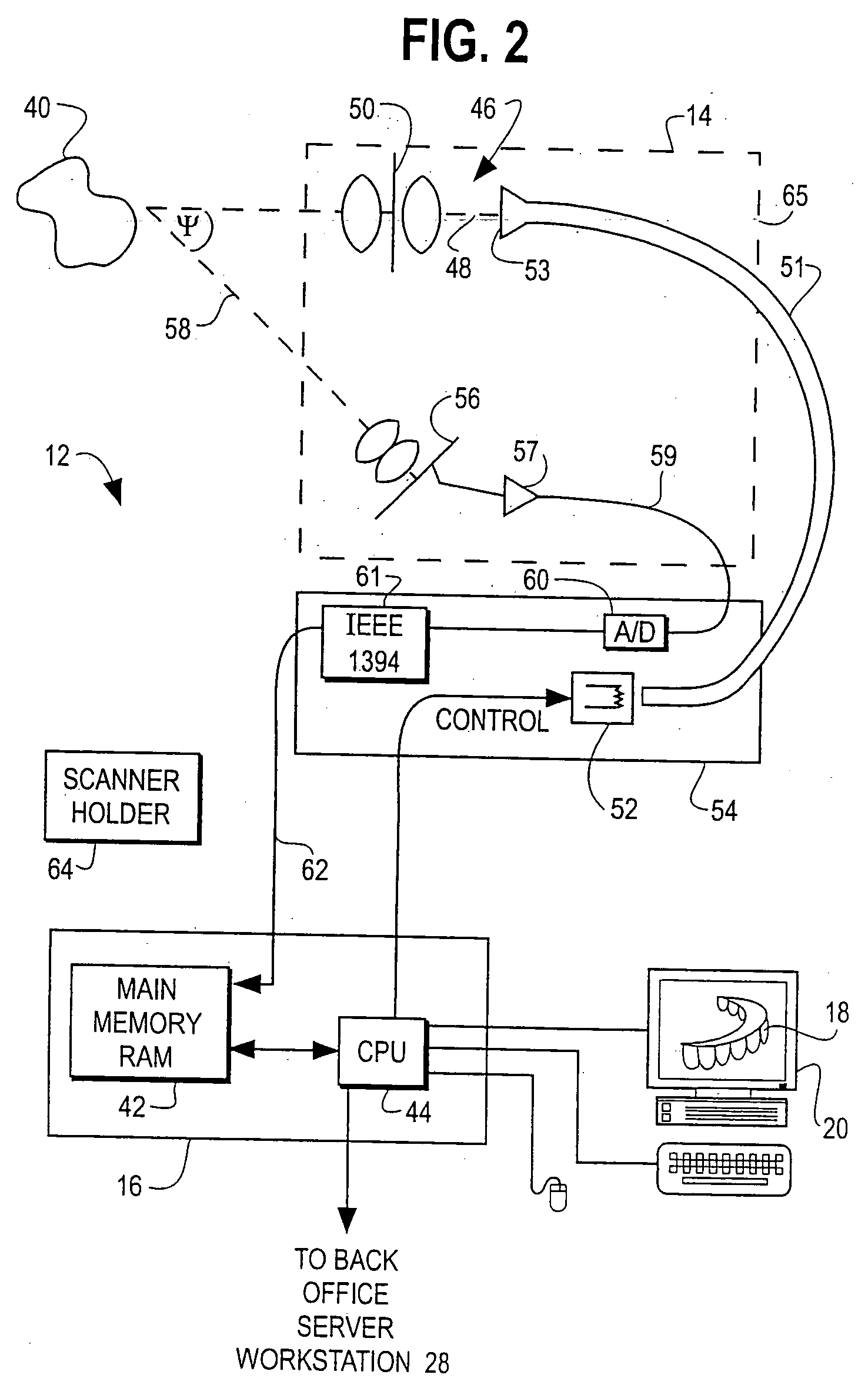
[0019] This invention relates generally to a scanning system that captures a series of two-dimensional images containing surface information of objects. The scanning system generates an accurate three-dimensional computer model of the object from the captured images. The invention also relates to method for deriving the three-dimensional information from the captured images.

[0020] The inventive scanning system and method can be used to analyze the surface and three-dimen...


PUM


Abstract

A scanning system includes a hand-held scanning device that generates two-dimensional images of a pattern reflected off an object. The system also includes a memory and processing unit. The memory stores a calibration table for the scanner and received scanned bitmap images. The processing unit generates three-dimensional information as to a scanned object. The scanning can be performed without knowledge or even precise control of the position of the object relative to the scanner. Random movement of the object during scanning is also possible. For example, the scanner is simply swept over the surface of the object by hand. Three-dimensional information of the object is obtained from the captured images using a calibration table for the scanner. A method of calibration of the scanner in X, Y and Z directions is also described. The scanner can be used for a variety of purposes, including medical and industrial purposes. The illustrated embodiment is in-vivo scanning of human teeth for purposes of orthodontic treatment planning and diagnosis.

Description

CROSS-REFERENCE TO RELATED APPLICATIONS [0001] This application is a continuation-in-part application of the following pending U.S. patent applications: [0002] Ser. No. 09 / 254,755 filed Mar. 8, 1999 (MBHB 00-1029); [0003] Ser. No. 09 / 254,843 filed Mar. 11, 1999 (MBHB 00-1031); [0004] Ser. No. 09 / 673,963 filed Nov. 20, 2000 (MBHB 00-1033); [0005] Ser. No. 09 / 452,031 filed Nov. 30, 1999 (MBHB 00-1022); [0006] Ser. No. 09 / 452,034 filed Nov. 30, 1999 (MBHB 00-1020); [0007] Ser. No. 09 / 560,131 filed Apr. 28, 2000 (MBHB 00-1000); [0008] Ser. No. 09 / 560,132 filed Apr. 28, 2000 (MBHB 00-1001); [0009] Ser. No. 09 / 560,583 filed Apr. 28, 2000 (MBHB 00-1002); [0010] Ser. No. 09 / 560,645 filed Apr. 28, 2000 (MBHB 00-1004); [0011] Ser. No. 09 / 560,644 filed Apr. 28, 2000 (MBHB 00-1005); [0012] Ser. No. 09 / 560,133 filed Apr. 28, 2000 (MBHB 00-1006); [0013] Ser. No. 09 / 560,641 filed Apr. 28, 2000 (MBHB 00-1023); [0014] Ser. No. 09 / 560,584 filed Apr. 28, 2000 (MBHB 00-1025); [0015] Ser. No. 09 / 560.134...

Claims


Application Information

Patent Timeline
Patent Type & Authority Applications(United States)
IPC IPC(8): A61C7/00A61C7/14A61C9/00A61C13/00A61F2/30G06T17/00
CPCA61C7/00A61C7/002A61C7/146A61C9/004G06T17/00A61F2002/30953G01B11/2504G01B11/2518G06T7/0057A61C13/0004A61C9/006B33Y50/00B33Y80/00G06T7/521
Inventor RUBBERT, RUDGERWEISE, THOMASSPORBERT, PEERIMGRUND, HANSGEERDES, HANS-FLORIANPFEIL, LUTZSEE, PETER
Owner ORAMETRIX
Why Eureka
Try Eureka