Optical signal converter, optical encoder, optical decoder, and optical code division multiplexing communication apparatus

a communication apparatus and optical code technology, applied in the field of optical signal converters, optical encoders, optical decoders, optical code division multiplexing communication apparatuses, can solve the problems of limiting data rate, transmission distance, and encoding signals of the same wavelength that cannot be multiplexed strictly in the same time slot, so as to achieve satisfactory encoding/decoding characteristics, high-performance optical code division multiplexing communication, and suppression of interferen

Active Publication Date: 2005-04-28
MARVELL ASIA PTE LTD
View PDF8 Cites 28 Cited by
  • Summary
  • Abstract
  • Description
  • Claims
  • Application Information

AI Technical Summary

Benefits of technology

[0008] The present invention has been made in view of the problems mentioned above, and it is an object of the invention to provide an encoder / decoder which suppress the interference among optical encoded signals to present satisfactory encoding / decoding characteristics, and a high performance optical code division multiplexing communication apparatus. It is another object of the present invention to provide a high performance encoder / decoder and optical code division multiplexing communication apparatus which have satisfactory characteristics even at a data rate having a period equal to or shorter than a duration time.

Problems solved by technology

However, there has been no example in which encoded signals of the same wavelength are multiplexed strictly in the same time slot.
Therefore, when signals spread in the time axis are overlapped with one another, interference among optical pulses can damage the transmission characteristics, limit the data rate, transmission distance and the like, and also causes other problems.
Also, if encoded signals of the same wavelength cannot be multiplexed in the same time slot as described above, an upper limit for a data rate applicable in an optical communication system is determined by an encoder, so that the flexibility of the optical communication system is limited by the encoder.
However, a simple increase in the number of code chips would result in an increase in the length of the SSFBG, thereby further limiting the data rate to which the SSFBG can be applied.

Method used


Image

  • Optical signal converter, optical encoder, optical decoder, and optical code division multiplexing communication apparatus
  • Optical signal converter, optical encoder, optical decoder, and optical code division multiplexing communication apparatus
  • Optical signal converter, optical encoder, optical decoder, and optical code division multiplexing communication apparatus

Examples


first embodiment

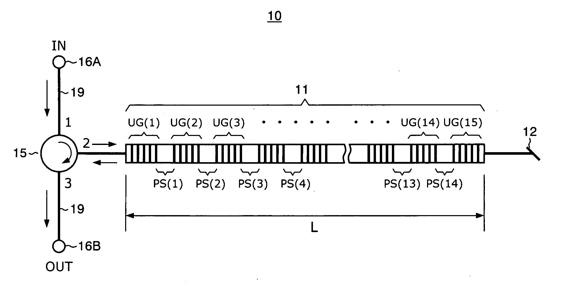
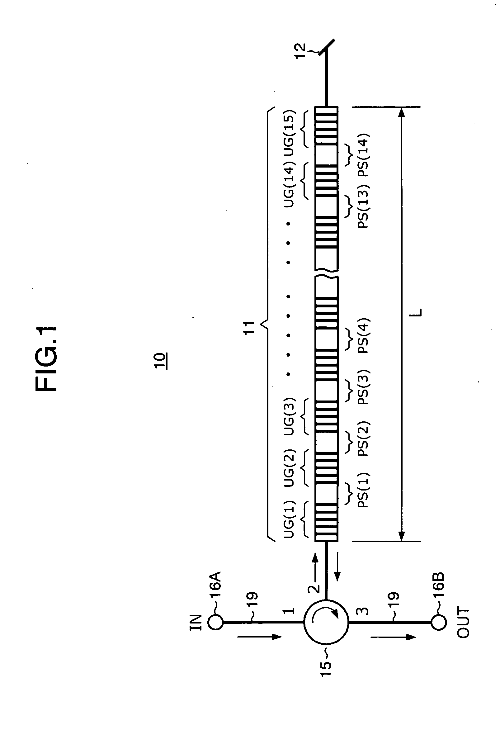
[0049]FIG. 1 is a block diagram illustrating the configuration of an optical encoding apparatus 10 according to a first embodiment of the present invention.

[0050] An optical encoder used herein is configured as a combination of a multiple phase shifted fiber Bragg grating (FBG) and an optical circulator. In more detail, the optical encoding apparatus 10 comprises an optical encoder (hereinafter, also simply referred to as an “encoder”) 11 and an optical circulator 15. An optical signal input to a light input terminal 16A of the optical encoding apparatus 10 is led to a first port of the optical circulator 15 through an optical fiber 19, passes a second port of the optical circulator 15, and is reflected by the optical encoder 11. An optical terminator or an optical attenuator 12 is connected to a dead-end terminal of the optical encoder 11 for providing attenuation approximately of −50 dB. The reflected optical signal from the optical encoder 11 is led to a light output terminal 16...

second embodiment

[0075]FIG. 9 is a block diagram illustrating the configuration of an optical code division multiplexing (OCDM) communication apparatus 35 according to a second embodiment of the present invention. The optical code division multiplexing communication apparatus 35 comprises an OCDM transmitter 36, an optical fiber 37, and an OCDM receiver 38. The OCDM transmitter 36 comprises optical pulse signal generators 31A, 31B; optical circulators 15A, 15B; optical encoders 11A, 11B; optical terminators 12A, 12B; and an optical coupler 33.

[0076] The optical pulse signal generator 31A, the optical circulator 15A, the optical terminator 12A, and the optical encoder 11A make up a first transmission channel, while the optical pulse signal generator 31B, the optical circulator 15B, the optical terminator 12B, and the optical encoder 11B make up a second transmission channel. The optical pulse signal generators 31A, 31B generate optical RZ signals which have substantially the same wavelength, an opti...

third embodiment

[0080] In the first and second embodiments described above, the total duration of an optical pulse signal encoded by the optical encoder does not exceed the time period corresponding to the transmission data rate. Specifically, since the optical encoder has the total duration of approximately 360 ps as mentioned above, optical pulses at the same wavelength encoded with the same code will not overlap with one another, as schematically shown in FIG. 12, when the data rate is set to be 2.5 Gps. FIG. 12 shows an encoded optical signal waveform with respect to the time axis, where optical waveforms of the respective bits are sequentially represented such as a first bit, a second bit, a third bit, . . . (bit-1, bit-2, bit-3, . . . ). As described above, the optical waveform of each bit has a time width (total duration) of approximately 360 ps, and a time slot has a time width of 400 ps at the data rate of 2.5 Gps, so that the optical waveforms of the respective bits will not overlap with ...


PUM


Abstract

An optical signal encoder / decoder includes a grating waveguide having an identical number of uniform pitch gratings to the number of code chips of a binary phase optical code, the uniform pitch gratings being formed in a waveguide direction to reflect light of a predetermined wavelength. Here, adjacent gratings corresponding to a position at which the optical code value changes are disposed a spacing apart from each other to give a phase shift of (2m+1)π / 2 to the light, and the remaining adjacent gratings are disposed a spacing apart from each other to give a phase shift of nπ to the light (m, n: integer).

Description

BACKGROUND OF THE INVENTION [0001] 1. Field of the Invention [0002] The present invention relates to an optical signal converter, an optical encoder, an optical decoder, an optical code division multiplexing communication apparatus, and the like for use in optical code division multiplexing communications. [0003] 2. Description of the Related Art [0004] In recent years, the communication traffic demands have been rapidly increased due to the widespread proliferation of the Internet. The optical multiplexing communication technologies have been so far developed from an optical time domain multiplexing (OTDM) communication scheme to a wavelength division multiplexing (WDM) communication scheme to increase the communication capacities. It is an optical code division multiplexing (OCDM) communication scheme which is expected as the next generation optical multiplexing communication scheme. The OCDM communication scheme is characterized by the capability to set a plurality of communicati...

Claims


Application Information

Patent Timeline
Patent Type & Authority Applications(United States)
IPC IPC(8): H04B10/2581H04J14/00
CPCH04J14/005H04B10/2581
Inventor NISHIKI, AKIHIKOOSHIBA, SAEKO
Owner MARVELL ASIA PTE LTD
Why Eureka
Try Eureka