Electric motor with an air duct

Active Publication Date: 2005-04-28
HILTI AG
View PDF6 Cites 1 Cited by
  • Summary
  • Abstract
  • Description
  • Claims
  • Application Information

AI Technical Summary

Benefits of technology

[0013] Advantageously, the resiliently displaceable fixing means is connected with the shroud by a leaf spring securable with one of its ends to a radially inwardly located, connection point. Thereby, with the air duct formed as a one-piece part, the radially outwardly located, axially resiliently displaceable, fixing means can be formed technologically easy.
[0015] Advantageously, there are provided two locking means which are, preferably, arranged diametrically opposite with respect to the rotor rotational axis. Thereby, the bending torque generated upon tightening of locking bolts for securing the stator in the housing is reduced.

Problems solved by technology

The securing of a stator with the air duct cannot be carried out.

Method used


Image

  • Electric motor with an air duct
  • Electric motor with an air duct

Examples


Embodiment Construction

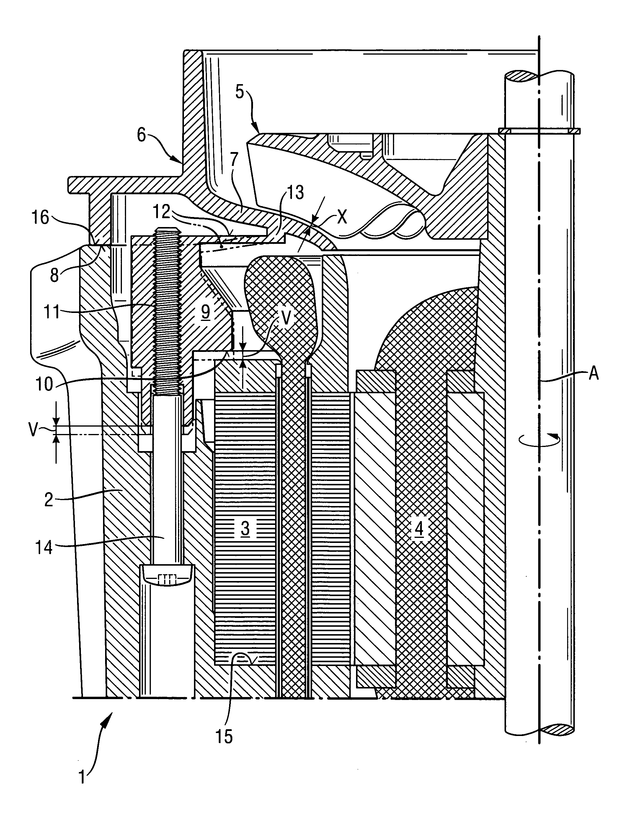
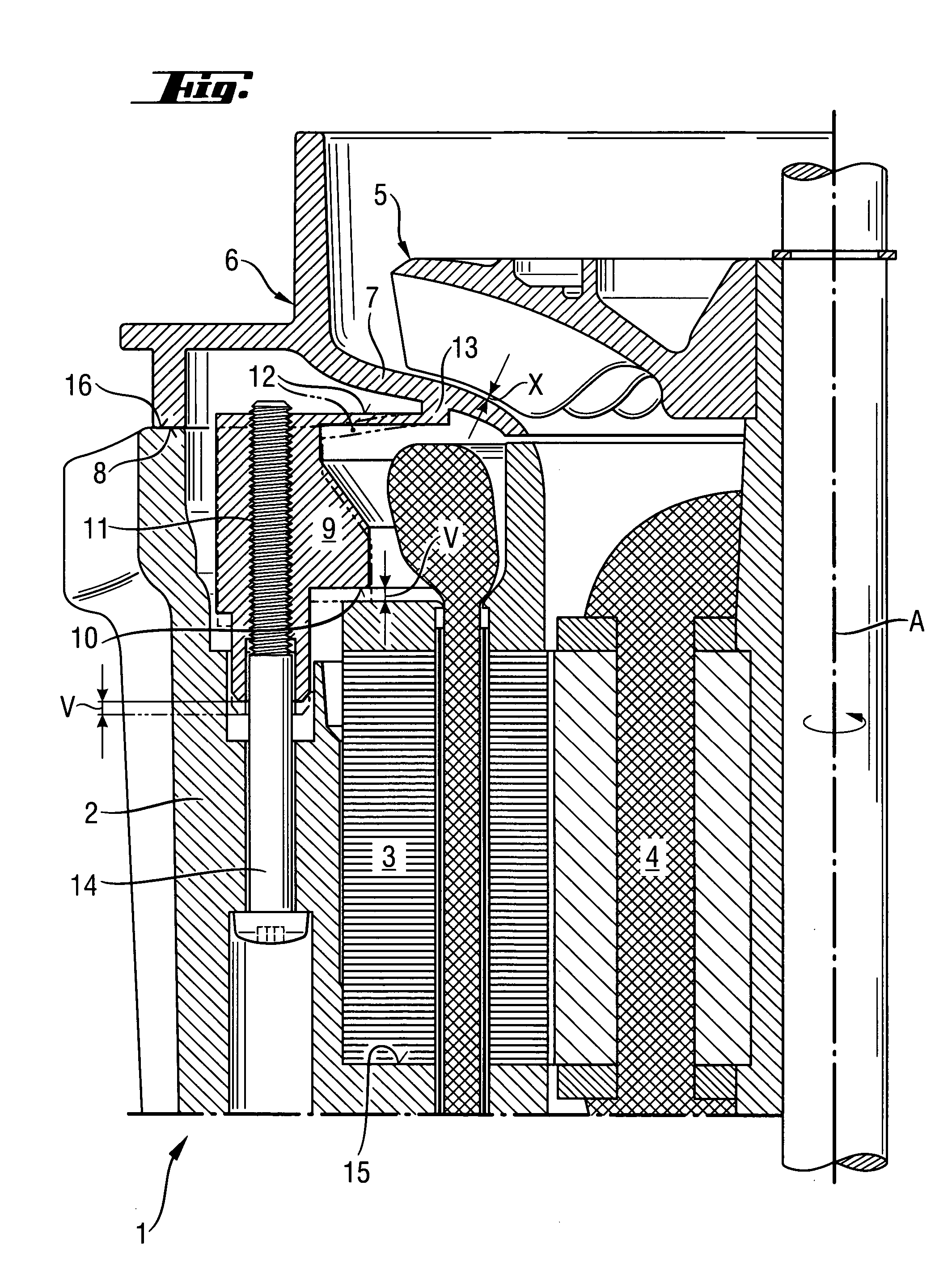
[0019] An air-cooled motor according to the present invention, which is shown in the drawing, includes a housing 2, a stator 3 secured in the housing 2, and a rotatable, about an axis A, rotor 4 on which a fan impeller 5 is arranged. Between the rotor 4 and the impeller 5, an annular air duct 6 with a rotationally symmetrical shroud 7 is arranged. The shroud 7 is spaced from the impeller 5 by a narrow slot having a width X. The one-piece air duct also forms a dimensionally stable housing stop 8 and an axially resiliently displaceable fixing means 9 that includes a stator stop 10 facing in the same direction as the housing stop 8. The fixing means 9 further has locking means in form of two inner threads 11 (of which only one thread is shown) for locking bolts 14 and which extend parallel to the axis A about which the rotor 3 rotates. A leaf spring 12, which is formed by the air duct 6, connects the fixing means 9 with the shroud 7 at a located radially inwardly, connection point 13. ...


PUM


Abstract

An electric motor includes a stator (3) secured in the motor housing (2), a rotatable rotor (4), a fan impeller (5) arranged on the rotor (4), and an annular air duct (6) arranged between the fan impeller (5) and the rotor (4) and having a shroud (7) spaced from the impeller (5) by a slot having an axial width (X), a dimensionally stable, with respect to the shroud (7), housing stop (8), an axially, resiliently displaceable fixing element (9) forming a stator stop (10) facing in a same direction as the housing stop (8), and a locking element.

Description

BACKGROUND OF THE INVENTION [0001] 1. Field of the Invention [0002] The present invention relates to an air-cooled electric motor, in particular, for a hand-held power tool, and having an air duct. [0003] 2. Description of the Prior Art [0004] The stator of an electric motor is formed of stacked sheet metal lamellas in order to prevent any eddy current losses in an a.c. field. The necessary discrete number of lamellas results, upon assembly, to a discrete lengths, with a length tolerance of about .5mm with a minimum one lamella. [0005] For removal of heat, which is generated during operation of the electric motor, in compact electrical motors which are preferably used in hand-held power tools, a cooling air stream is directed through a gap between the stator and the rotor. The air stream is generated by a fan impeller mounted on the rotor shaft. In order to increase the efficiency, the fan impeller is movable in a suitably shaped, air duct with a shroud, whereby a critical, axially ...

Claims


Application Information

Patent Timeline
IPC IPC(8): H02K5/20H02K9/06
CPCH02K9/06H02K5/20H02K5/207
Inventor BURGER, HELMUTSCHWARZ, HANSJOERGSCHMIDDUNSER, PETERLUEBKERT, ERNST-RUDOLF
Owner HILTI AG
Why Eureka
Try Eureka