Ultrasonic diagnostic apparatus

a technology probes, applied in the field of ultrasonic diagnostic equipment, can solve the problems of inability to observe a part at the back of a cauterized part from the position of a probe over a treated part, and achieve the effect of easy detection

Active Publication Date: 2005-04-28
TOSHIBA MEDICAL SYST CORP
View PDF8 Cites 158 Cited by
  • Summary
  • Abstract
  • Description
  • Claims
  • Application Information

AI Technical Summary

Benefits of technology

[0027] Another object of the invention is to provide clinically useful ultrasonic diagnostic equipment for assisting puncture wherein the end position of a puncture probe can be easily detected, a directi

Problems solved by technology

However, an ultrasonotomographic image by the puncture probe under the above-mentioned ultrasonic guidance cannot be sufficiently observed, operation for insertion into a target part is very difficult, and insufficiency in the stability of display and operability comes into question.
Besides, there is also a problem that the observation of a part at the back of a cauterized part from the position of a probe over a treated part is disabled because of the alteration of tissue by cauterization and generated bubbles.
However, in treatment using the ultrasonic diagnostic equipment depending upon only the above-mentioned guide mechanism of the conventional type puncture probe and the puncture adaptor, it comes into a large question that observation is enabled in only a direction in which the puncture probe related to the treatment is maintained in the slice width of an ultrasonic beam and the three-dimensional positional grasping is difficult.
In case the puncture probe is inserted, viewing a tomographic image by ultrasonic diagnostic equipment, there is a problem that a reflected wave having sufficient intensity by the puncture probe cannot be acquired and the stable and clear display of the position of the probe in the ultrasonotomographic image is difficult becaus

Method used


Image

  • Ultrasonic diagnostic apparatus
  • Ultrasonic diagnostic apparatus
  • Ultrasonic diagnostic apparatus

Examples


4 embodiment

1-4 Embodiment

[0105] Referring to FIGS. 5 and 6A to 6F, a 1-4 embodiment will be described below.

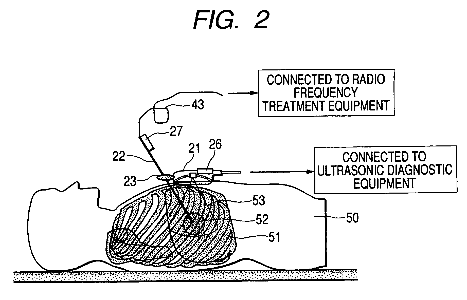
[0106] In this embodiment, first an ultrasonic probe 21 is independently placed on the surface of the body of a patient as shown in FIG. 5 without utilizing a puncture adaptor, a tumor of a target internal organ, its ambient internal organs and its ambient blood vessels are scanned, an inserted position and a puncture path are observed and determined. A position in which the tumor can be caught in a field of view of an ultrasonotomographic image and a clear tomographic image of a target part is acquired is a therapeutic observation position.

[0107] Next, the ultrasonic probe 21 is held in the therapeutic observation position, the end of a puncture probe 22 provided with a position sensor B 27 is located in the vicinity of the surface of the body of a patient 50, and the puncture probe is set in its inserted direction. FIG. 6B is a schematic drawing in which the tomographic image 71 in t...

5 embodiment

1-5 Embodiment

[0117]FIGS. 7, 8, 9 and 10 are schematic drawings showing an embodiment of monitor display by the ultrasonic diagnostic equipment according to the invention. In this embodiment, the last tomographic image acquired before cautery or in the last cautery and a real-time tomographic image showing an inserted puncture probe during cautery are simultaneously displayed on two screens in various display modes of a monitor.

[0118] In a first display example shown in FIG. 7, a tomographic image 81 formerly acquired and recorded is displayed including an image of a tumor 82 verified as a therapeutic object on the left side for example of the monitor 32. On the right side, a real-time tomographic image 83 observed by an ultrasonic probe 21 is displayed including an image of the tumor 84 treated by the puncture probe 22.

[0119] Next, when the puncture probe 22 provided with a position sensor B 27 is set in the vicinity of the surface of the body over a target internal organ in an i...

6 embodiment

1-6 Embodiment

[0132] Referring to a schematic drawing shown in FIGS. 11A and 11B, a 1-6 embodiment of the invention will be described below.

[0133] A three-dimensional ultrasonographic image by the ultrasonic diagnostic equipment according to the invention is not limited to an image three-dimensionally scanned by manually operating an ultrasonic probe and acquired by reconstructing three-dimensional tomographic image data based upon a two-dimensional tomographic image. A three-dimensional tomographic image by a mechanical three-dimensional ultrasonic probe for three-dimensionally scanning by the mechanical parallel motion or the mechanical rotational motion of the ultrasonic probe or a three-dimensional tomographic image by an electronic three-dimensional ultrasonic probe for electronically scanning three-dimensionally based upon a two-dimensional array probe can be similarly applied for a three-dimensional tomographic image by the ultrasonic diagnostic equipment according to the in...


PUM


Abstract

Ultrasonic diagnostic equipment is equipped with an ultrasonic probe that transmits/receives ultrasound to/from an examined body, a probe position sensor that detects the position and the direction of the ultrasonic probe, an image generator that generates image data based upon the output of the ultrasonic probe, a probe position sensor that detects the position and the direction of a puncture probe inserted into the examined body, a display image generator that generates the data of a display image in which the end position of the puncture probe is fixed to a specific position in an image display area according to the position and the direction of the ultrasonic probe and the position and the direction of the puncture probe based upon the image data and a display for displaying the display image in the image display area.

Description

CROSS-REFERENCE TO RELATED APPLICATIONS [0001] This application is based upon and claims the benefit of priority from prior Japanese Patent Applications No. 2003-294925, filed Aug. 19, 2003; and No. 2004-142383, filed May 12, 2004, the entire contents of both of which are incorporated herein by reference. BACKGROUND OF THE INVENTION [0002] 1. Field of the Invention [0003] The present invention relates to ultrasonic diagnostic equipment for guiding the insertion of a puncture probe or a treatment probe such as a PEIT probe, a radio frequency puncture probe and a microwave puncture probe into a target part. [0004] 2. Description of the Related Art [0005] For treatment for a tumor such as a cancer of an internal organ, a puncture probe or a treatment probe is often inserted into a target part by ultrasonic guidance and the insertion is called ultrasonically guided puncture and others. [0006] In case these probes are inserted, a guide mechanism for setting the insertion direction of the...

Claims


Application Information

Patent Timeline
IPC IPC(8): A61B8/08A61B17/34A61B18/14A61B19/00
CPCA61B8/0833A61B17/3403A61B18/148A61B19/5244A61B2019/566A61B2019/507A61B2019/5276A61B2019/5295A61B2017/3413A61B8/4254A61B34/20A61B2034/107A61B2034/256A61B2090/367A61B2090/378
Inventor MINE, YOSHITAKAYAMAGATA, HITOSHI
Owner TOSHIBA MEDICAL SYST CORP
Why Eureka
Try Eureka