Transendoscopic needle assembly

a needle and endoscope technology, applied in the field of transendoscopic needle assembly, can solve the problems that the flexible needle assembly conventions have not provided satisfactory means for balancing the necessary flexibility, and achieve the effect of increasing rigidity

Inactive Publication Date: 2005-04-28
WANG KO PEN
View PDF15 Cites 31 Cited by
  • Summary
  • Abstract
  • Description
  • Claims
  • Application Information

AI Technical Summary

Benefits of technology

[0006] Optionally, the device also includes a hard tip fixed to the distal end of the outer tubular member, the tip including a bearing surface on the proximal end thereof. The needle member comprises a hollow needle and a limiting member rigidly associated with the needle and contacting the bearing surface of the tip member in the first and second extended positions. Preferably, the first spring section comprises a first wavelength and the second spring section comprises a second wavelength different from (greater than or less than) the first wavelength in the retracted and first extended positions. The second spring section has a third wavelength in the second extended position, the third wavelength being less than the second wavelength. Preferably, the stylet passes into and through an inner volume defined by the second spring section whether the device is in the retracted, the first or the second extended positions. Similarly, the stylet preferably passes into the inner volume defined by the first spring section in the retracted and first extended positions, and passes through the inner volume thereof in the second extended position. Optionally, the stylet extends into the needle in the second extended position in order to provide increased rigidity.

Problems solved by technology

A particular problem in utilizing a flexible bronchoscopic needle is that the needle assembly must be flexible enough to allow the physician to maneuver the assembly to the target site, but yet rigid enough to allow penetration of the needle into the target tissue.
Conventional flexible needle assemblies have not provided satisfactory means for balancing the necessary flexibility with the desired rigidity as the needle is directed toward the target tissue.

Method used


Image

  • Transendoscopic needle assembly
  • Transendoscopic needle assembly
  • Transendoscopic needle assembly

Examples


Embodiment Construction

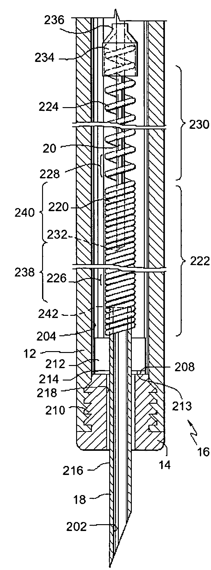
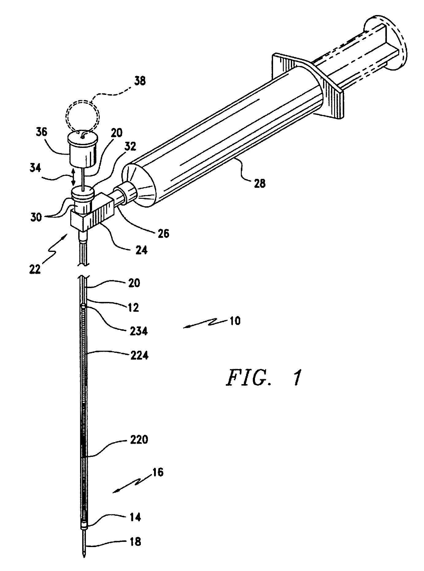
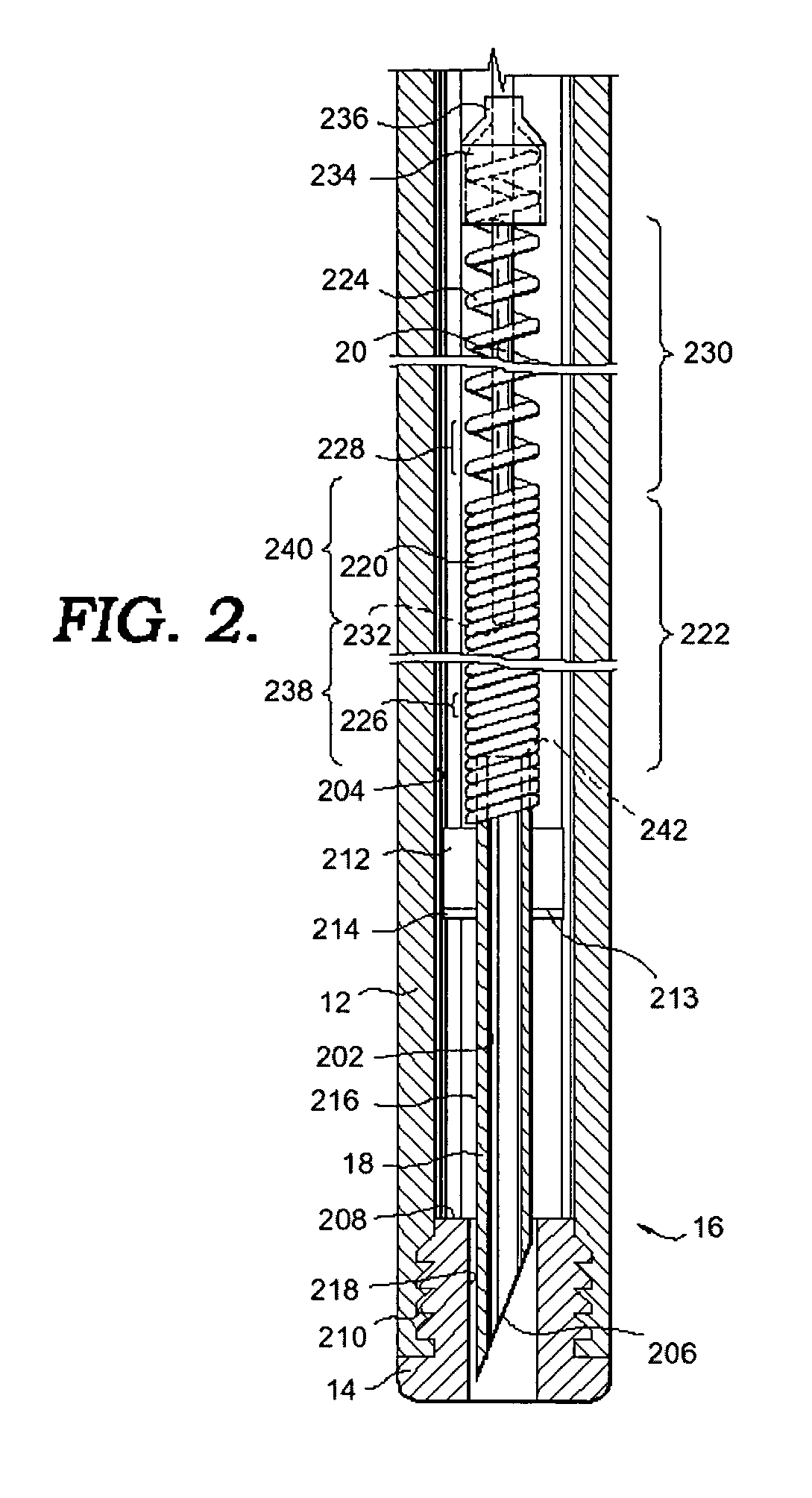
[0015] The present invention is directed to a medical device, which includes a flexible outer tubular member, e.g., a flexible catheter, having proximal and distal ends. As used herein, the proximal end of a component of the medical device is the end closest to the administering physician during normal use, and the distal end is the end of the component farthest away from the administering physician, e.g., the end closest to the target site, during normal operation. A flexible inner member is slidably and coaxially received within the outer tubular member. The inner member includes a flexible member, e.g., a flexible stylet, housed within the proximal end of the outer tubular member; a first spring member or section having proximal and distal ends and being oriented adjacent the distal end of the outer tubular member; and a second spring member or section oriented between the stylet and the first spring section. A retractable hollow needle member is coupled to the distal end of the ...


PUM


Abstract

A medical device for obtaining biopsy tissue samples is provided. The device includes a flexible outer tubular member having proximal and distal ends, and a flexible inner member slidably and preferably coaxially received within the outer tubular member. The inner member includes a flexible member adjacent the proximal end of the outer tubular member, a first spring section having proximal and distal ends and being oriented adjacent the distal end of the outer tubular member, and a second spring section therebetween. A retractable hollow needle member or other specimen collection device is coupled to the distal end of the first spring section. The device has a retracted position wherein the needle member is retractably housed within the outer tubular member, a first extended position wherein the needle member is at least partially deployed beyond the distal end of the outer tubular member and the second spring section is in an uncompressed state, and a second extended position wherein the second spring section is in a compressed state.

Description

FIELD OF THE INVENTION [0001] This invention relates generally to a transendoscopic needle assembly for use with a flexible bronchoscope, endoscope or any other type of body cavity scope, and more particularly to an improved transendoscopic needle assembly and operating mechanism for obtaining tissue samples from within the body. BACKGROUND OF THE INVENTION [0002] Conventionally, when biopsies were desired to be taken of the lymph nodes, for example, so as to aid in the diagnosis of carcinoma, the prior techniques would all typically utilize a substantially rigid needle and penetrate the body via percutaneous entry. For example, U.S. Pat. Nos. 3,630,192 and 3,628,524 each to Jamshidi disclose biopsy needles suitable for percutaneous entry. More recently, less invasive flexible biopsy instruments which do not require percutaneous entry have been described. U.S. Pat. No. 4,249,541 to Pratt discloses that a flexible biopsy instrument can be utilized in combination with a fiberoptic bro...

Claims


Application Information

Patent Timeline
Patent Type & Authority Applications(United States)
IPC IPC(8): A61B10/00A61B10/02A61B10/04A61B17/34
CPCA61B10/04A61B2010/045A61B2010/0208A61B17/3496
Inventor WANG, KO-PEN
Owner WANG KO PEN
Why Eureka
Try Eureka