Method and apparatus for rebuilding gas turbine engines

a gas turbine engine and gas turbine technology, applied in mechanical equipment, machines/engines, manufacturing tools, etc., can solve the problems of affecting the clamping mechanism may inhibit the operation of grinding machines, etc., and the clamping mechanism is generally much more expensive. , the effect of reducing the cost of fixing

Active Publication Date: 2005-05-05
GENERAL ELECTRIC CO
View PDF14 Cites 68 Cited by
  • Summary
  • Abstract
  • Description
  • Claims
  • Application Information

AI Technical Summary

Problems solved by technology

However, because the dovetail serrations may be small, in many applications, the clamping mechanisms may inhibit operation of the grinding machines.
However, because such fixtu

Method used


Image

  • Method and apparatus for rebuilding gas turbine engines
  • Method and apparatus for rebuilding gas turbine engines
  • Method and apparatus for rebuilding gas turbine engines

Examples


Embodiment Construction

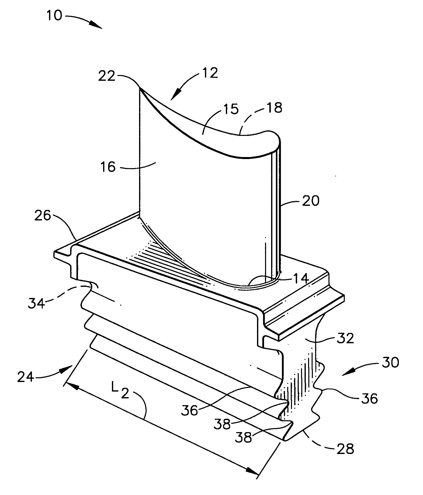
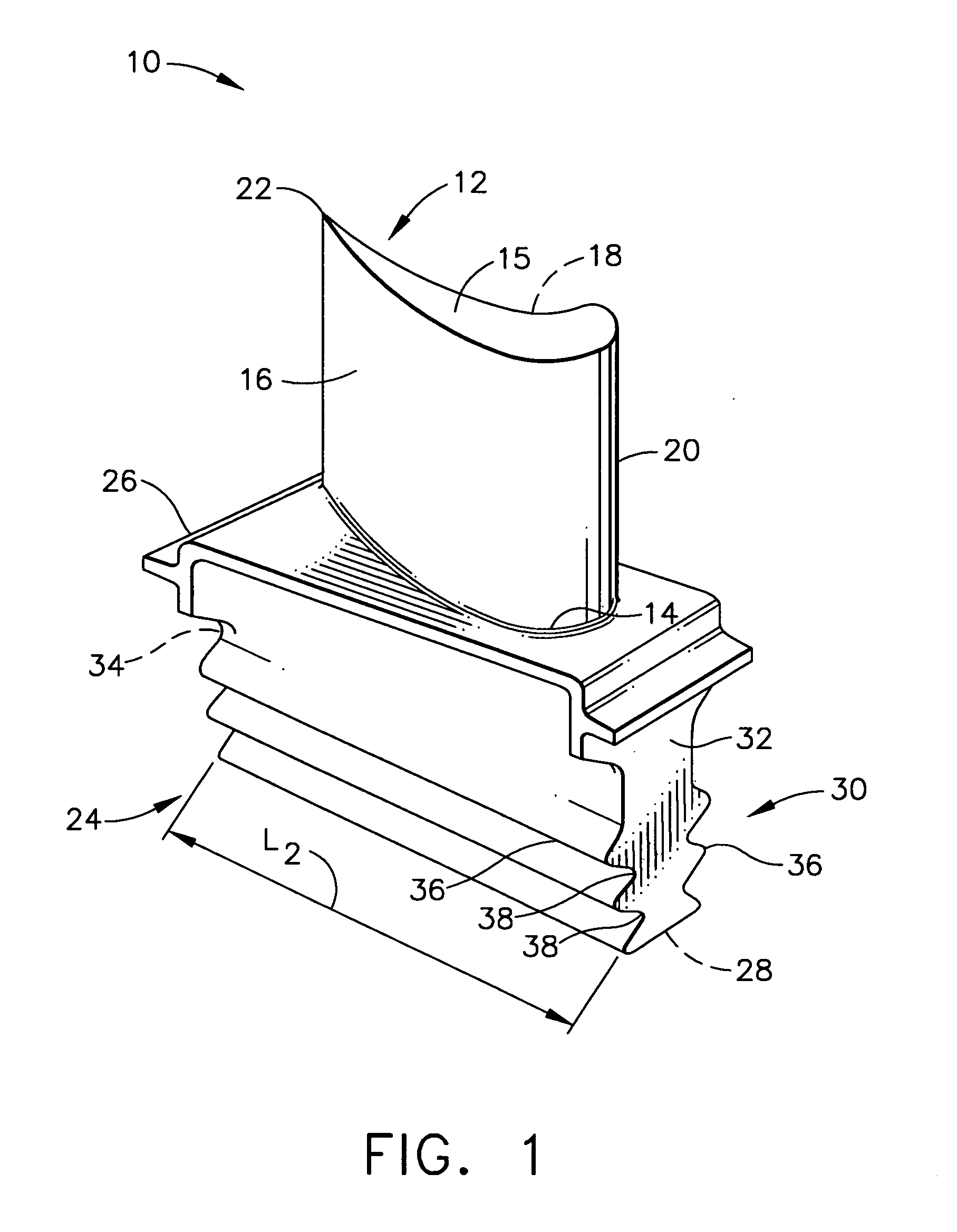
[0012]FIG. 1 is a perspective view of an exemplary turbine blade 10 that may be used with a gas turbine engine (not shown). Blade 10 includes an airfoil 12 that extends radially outward from a blade root 14 to an airfoil tip 15. Airfoil 12 includes a first contoured sidewall 16 and a second sidewall 18. Sidewalls 16 and 18 are joined at a leading edge 20 and at an axially-spaced trailing edge 22.

[0013] Blade 10 also includes an integral dovetail 24 that is used for mounting blade 10 in a rotor or disk that has a complimentarily dovetail-shaped slot (not shown) for receiving dovetail 24. Dovetail 24 is tapered from a platform 26 proximate blade root 14 to a radially inner surface 28, and includes a plurality of serrations 30 defined therein. Serrations 30 extend from a leading edge side 32 of dovetail 24 to a trailing edge side 34. Serrations 30 create a wavelike cross-sectional profile for dovetail 24 which has a series of alternating peaks 36 and valleys 38.

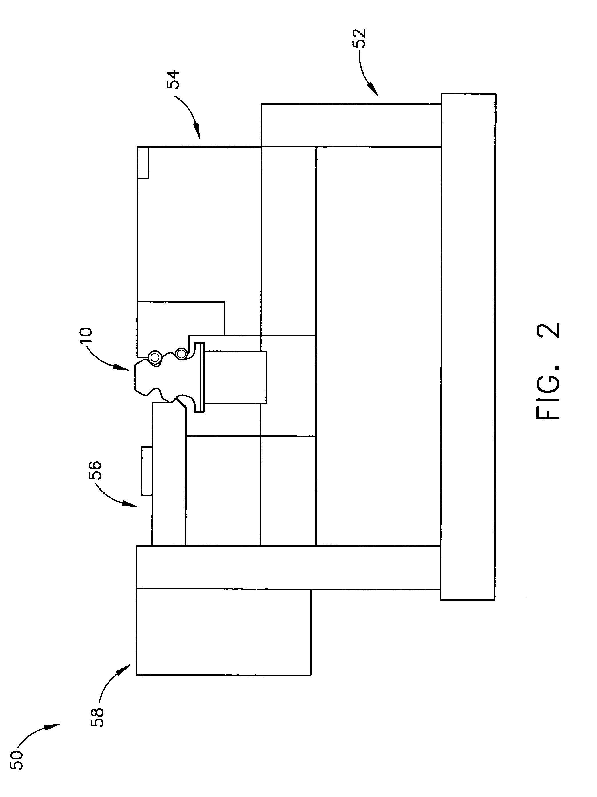
[0014]FIG. 2 is a sche...


PUM

PropertyMeasurementUnit
Lengthaaaaaaaaaa

Abstract

A method for repairing a turbine blade for a gas turbine engine is provided. The method includes securing the blade into a clamping fixture, obtaining a zero reference from a gauging surface on the clamping fixture, coupling the clamping fixture to a grinding machine, and grinding the blade based on the zero reference.

Description

BACKGROUND OF THE INVENTION [0001] This invention relates generally to gas turbine engines, and more specifically to turbine blades used in gas turbine engines. [0002] In at least some gas turbine engines, turbine blades used within the engine are cast to an approximate final shape. Portions of the turbine blades, including, but not limited to, a root portion, are then shaped to a final desired form by a shaping technique, such as grinding. The finished turbine blades are assembled into a turbine disk or rotor, such that a “dovetail” formed on each turbine blade engages a complimentarily shaped slot on the turbine disk. [0003] Generally, turbine blades are constructed from a high-temperature, high-strength alloy that is adapted to withstand the temperatures and stresses imposed on the parts of a turbine assembly. Because of the high cost of materials, casting operations, and finishing operations, some turbine blades, after being in service, are refurbished to restore the original ae...

Claims


Application Information

Patent Timeline
IPC IPC(8): B23P6/00B24B19/14B24B41/06F01D5/00F01D25/28
CPCB23P6/002B23Q3/063B24B19/14B24B41/06F01D5/005F01D25/285Y10T29/53435F05D2230/80Y10T29/37Y10T29/49998Y10T29/49895Y10T29/49318F05D2230/64
Inventor POWERS, JOHN MATTHEWDORREL, BRIAN DUDLEY
Owner GENERAL ELECTRIC CO
Why Eureka
Try Eureka