
Spark plug center electrode assembly

a technology of center electrode and spark plug, which is applied in the manufacture of spark plugs, spark plugs, machines/engines, etc., can solve the problems of introducing new design and manufacturing difficulties, constantly subjecting spark plugs used in internal combustion engines to extreme temperatures and other potentially damaging elements, and economic impracticality

Inactive Publication Date: 2005-05-05
FEDERAL MOGUL WORLD WIDE
View PDF26 Cites 26 Cited by
  • Summary
  • Abstract
  • Description
  • Claims
  • Application Information

AI Technical Summary

Benefits of technology

[0007] The above-noted shortcomings of prior art electrode assemblies are overcome by the present invention which provides an electrode assembly for use in an ignition device such as a spark plug or igniter. According to one embodiment, the electrode assembly includes a center electrode and a precious metal insert. The center electrode and precious metal insert are secured to one another via a mechanical interlock and a vapor-vented weld. The vapor vented weld can take different forms, such as, for example, a peripheral weld which includes at least one interruption that permits trapped gases to escape from any space that exists between the center electrode and insert.

Problems solved by technology

Spark plugs used in internal combustion engines are constantly subjected to environments having extreme temperatures and other potentially damaging elements.
This provides a durable sparking surface without having to construct the entire electrode out of the precious metal, which could be economically impractical.
Although the use of a precious metal insert may improve the consumption resistance (operational lifetime) and performance characteristics (ignitability) of the spark plug, its use may introduce new design and manufacturing difficulties.
One of those difficulties involves the attachment of the insert to the firing tip in a manner capable of withstanding the extreme forces exerted upon it during use.
This stress can contribute to a failure of the weld such that the precious metal insert may separate from the center electrode.

Method used


Image

  • Spark plug center electrode assembly
  • Spark plug center electrode assembly
  • Spark plug center electrode assembly

Examples


Embodiment Construction

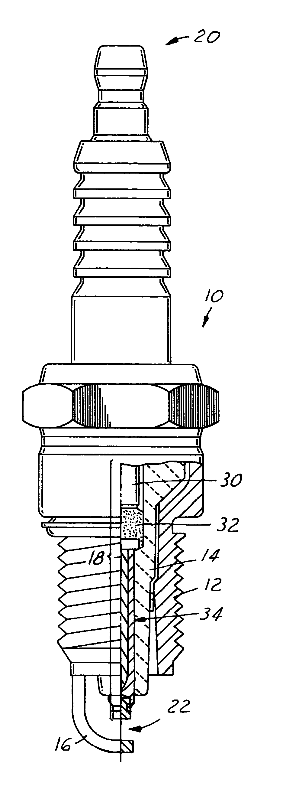
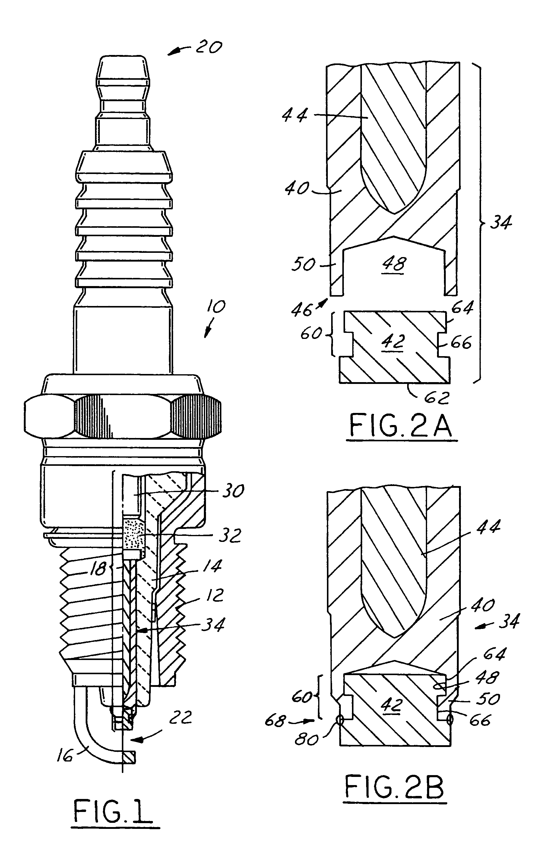
[0018] Referring to FIG. 1, there is seen a spark plug 10 generally including a metallic shell 12, an insulator 14, a ground electrode 16, and a center wire assembly 18. The metallic shell 12 includes a central bore in which the insulator 14 is fixed and the ground electrode 16 comprises a bent electrode that is welded or otherwise attached to a lower end of the shell 12. The metallic shell, insulator and ground electrode components are well known in the art, thus, a more detailed explanation of their structure and function is unnecessary. Center wire assembly 18 may comprise one of numerous combinations of components, and is used to deliver a high voltage ignition pulse from a terminal end 20, which is electrically coupled to a vehicle ignition system, to a spark gap 22, which is in communication with an ignition chamber. The particular combination of center wire assembly components seen here includes a terminal electrode 30, one or more conductive and / or resistive glass seals 32, ...


PUM


Abstract

A spark plug having a center electrode assembly that includes a center electrode and precious metal insert that is both mechanically interlocked and welded to the center electrode in a manner that permits trapped gases to escape from between the two components. Also disclosed is a method for manufacturing the same. During assembly, the precious metal insert is placed into a blind hole that extends axially into a lower end of the center electrode. Once in place, the center electrode is deformed around an enlarged head section of the insert to mechanically interlock the two components together. To further strengthen this attachment, the two components are welded together about their circumference. In one embodiment, the weld includes several interruptions that function as vapor vents for any gases that may be trapped. In other embodiments, a radially or an axially-extending vent hole is used in lieu of the weld interruptions.

Description

FIELD OF THE INVENTION [0001] The present invention relates generally to spark plugs, igniters, and other such ignition devices and, more particularly, to center electrode assemblies for such devices that utilize a precious metal insert at the firing tip. BACKGROUND OF THE INVENTION [0002] Spark plugs used in internal combustion engines are constantly subjected to environments having extreme temperatures and other potentially damaging elements. In order to combat such an aggressive environment and to protect the center electrode, certain precious metals are oftentimes employed at the firing end of the center electrode. These metals include platinum (Pt), iridium (Ir), and other noble metals exhibiting resistance to electrical erosion and chemical corrosion. It is known in the art to utilize these metals in the form of an insert; that is, a small, solid precious metal piece added to the lowermost tip of the center electrode. This provides a durable sparking surface without having to ...

Claims


Application Information

Patent Timeline
Patent Type & Authority Applications(United States)
IPC IPC(8): H01T13/39H01T21/02
CPCH01T21/02H01T13/39
Inventor LYKOWSKI, JAMES D.DOWNS, DARREN C.
Owner FEDERAL MOGUL WORLD WIDE
Learn More