Plasma display panel

a technology of display panel and plasma, which is applied in the direction of gas discharge vessel/container, gas-filled discharge tube, electrodes, etc., can solve the problems of severe damage to the electrode, and achieve the effects of increasing the aperture percentage, enhancing transmissivity, and increasing the discharge area

Inactive Publication Date: 2005-05-05
SAMSUNG SDI CO LTD
View PDF19 Cites 35 Cited by
  • Summary
  • Abstract
  • Description
  • Claims
  • Application Information

AI Technical Summary

Benefits of technology

[0010] The present invention provides a PDP having an increased aperture percentage and enhanced transmissivity, which cannot be achieved by th...

Problems solved by technology

In the DC type PDP, since electric charges are directly moved betw...

Method used


Image

  • Plasma display panel
  • Plasma display panel
  • Plasma display panel

Examples


Embodiment Construction

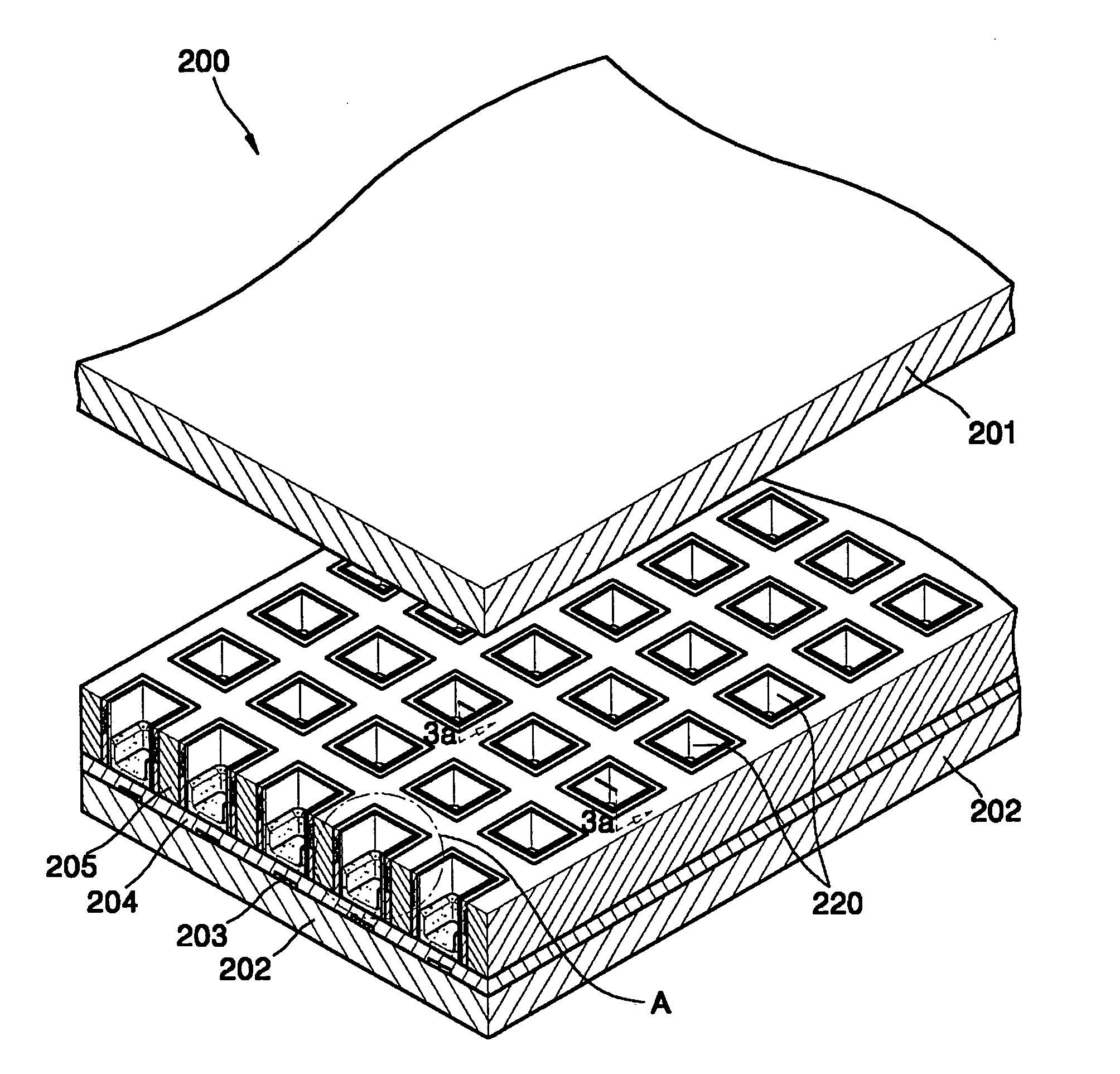
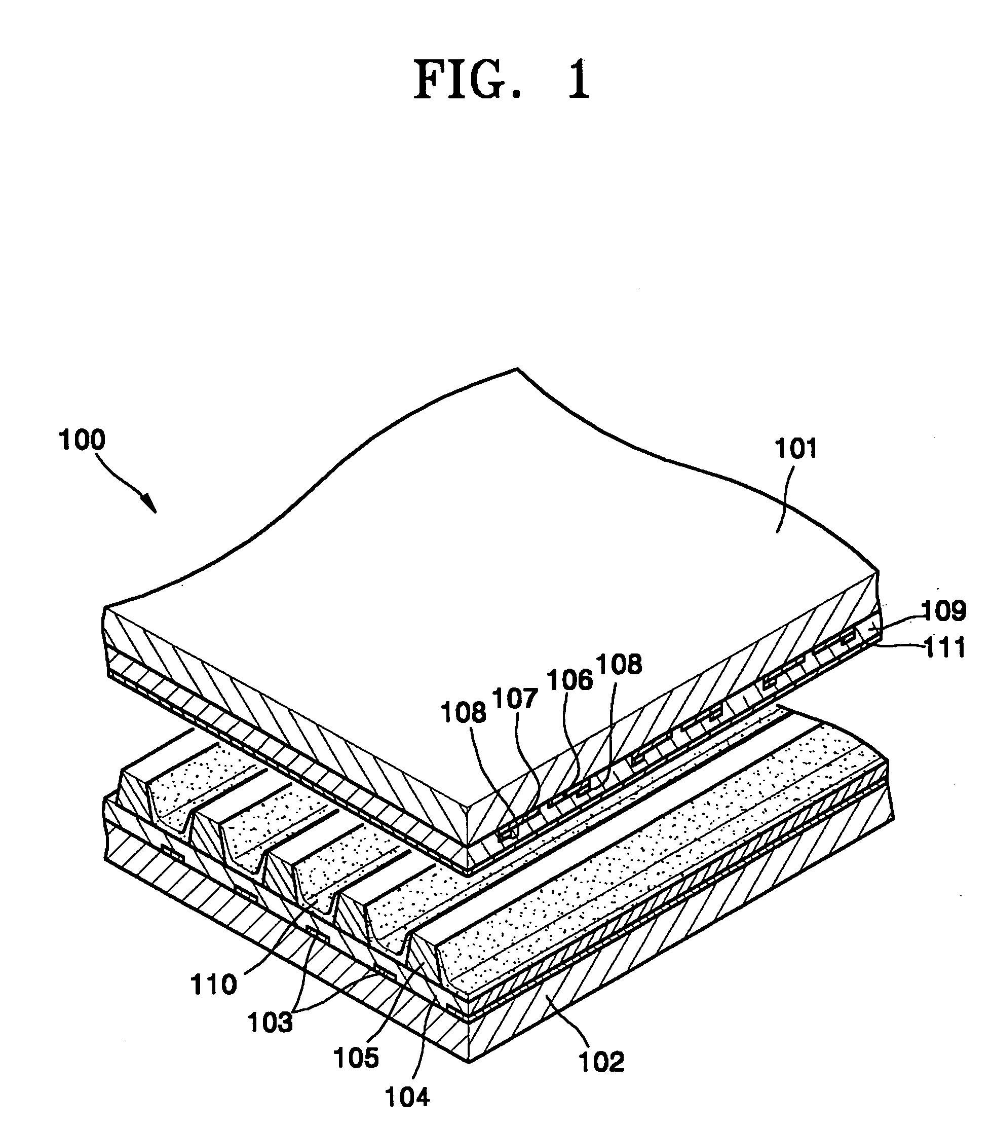
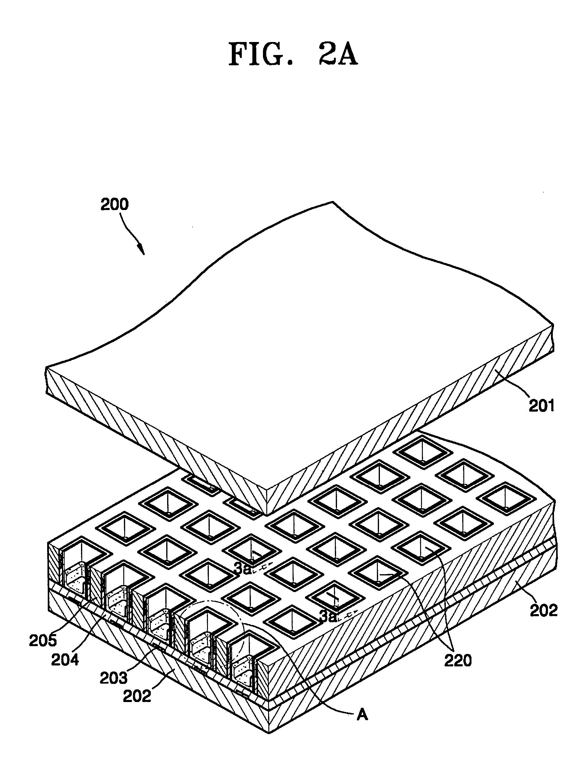
[0062] A conventional surface discharge PDP 100, including an AC type three-electrode surface discharge PDP, as shown in FIG. 1, includes a front substrate 101 through which visible lights emitted from a phosphor 110 in a discharge space, X and Y electrodes 107 and 108 are adapted to cause a discharge, bus electrodes 108, and a dielectric layer 109 and a protective layer sequentially formed thereon, are all provided on the front substrate 101, thereby lowering the transmissivity of visible light to approximately 60%. Also, in the conventional surface discharge PDP 100, discharge electrodes are formed on top of a discharge space, that is, on an internal surface of the front substrate 101 through which visible light passes, and discharge occurs on the internal surface to cause visible light to be dispersed, thereby lowering luminous efficiency. Also, if the conventional PDP 100 is used for an extended period of time, charge particles in a discharge gas can cause ion sputtering to the ...


PUM


Abstract

A plasma display panel includes a pair of substrates spaced apart from each other and facing each other, a visible light generator arranged between the pair of substrates, and an electrode layer adapted to apply the same potential to a plane arranged between the pair of substrates at a predetermined angle with respect to a direction perpendicular to the pair of substrates.

Description

CLAIM OF PRIORITY [0001] This application makes reference to, incorporates the same herein, and claims all benefits accruing under 35 U.S.C. §119 from an application for PLASMA DISPLAY PANEL earlier filed in the Korean Intellectual Property Office on Oct. 29, 2003 and there duly assigned Ser. No. 2003-76096.BACKGROUND OF THE INVENTION [0002] 1. Field of the Invention [0003] The present invention relates to a plasma display panel (PDP) adapted to display a character or an image using a gas discharge phenomenon, and more particularly, to a PDP having an increased surface on which a discharge is generated. [0004] 2. Description of the Related Art [0005] In recent years, PDPs have attracted considerable attention as the most promising next generation of flat display devices, because they have various advantageous features including a high image quality display, a very thin and lightweight design, and a wide-range viewing angle with a large screen, and they can be manufactured in a simpl...

Claims


Application Information

Patent Timeline
IPC IPC(8): H01J11/14H01J11/16H01J11/22H01J11/24H01J11/26H01J11/32H01J11/34H01J11/36
CPCH01J11/16H01J11/24H01J2211/323H01J11/36H01J2211/245H01J11/32
Inventor WOO, SEOK-GYUNKANG, KYOUNG-DOOYI, WON-JU
Owner SAMSUNG SDI CO LTD
Why Eureka
Try Eureka