

Plasma display panel
a plasma display and plasma technology, applied in the field of plasma display panels, can solve the problems of reducing the pdp b>10/b> display quality and insufficient pdp light, and achieve the effect of improving discharge efficiency and prolonging plasma extension
- Summary
- Abstract
- Description
- Claims
- Application Information
AI Technical Summary
Benefits of technology
Problems solved by technology
Method used
Image

Examples
first embodiment
[0033]FIG. 3 is a top view of the PDP of the first embodiment and FIG. 4 is a cross section view along the line 4-4′ of FIG. 3.
[0034] As shown in FIG. 3 and FIG. 4, a plurality of ribs 302 are disposed on a rear substrate 400 and form non-equilateral hexagonal discharge spaces in a delta configuration 304. Consequently, red non-equilateral hexagonal discharge space 305, green non-equilateral hexagonal discharge space 307 and blue non-equilateral hexagonal discharge space 309 are formed in a delta configuration. In the prefered embodiment, each rib 302 has two layers with different color. The top layer of the rib is black to enhance contrast and the bottom layer is white to increase luminance. The preferable height of each rib 308 is 100 μm-180 μm. Preferably, the non-equilateral hexagonal discharge space is symmetrical, and comprises four bevel sides 310, and two parallel vertical sides 308. Each vertical side 308 is preferably ½ the size of the bevel side 310, and more preferably ...
second embodiment
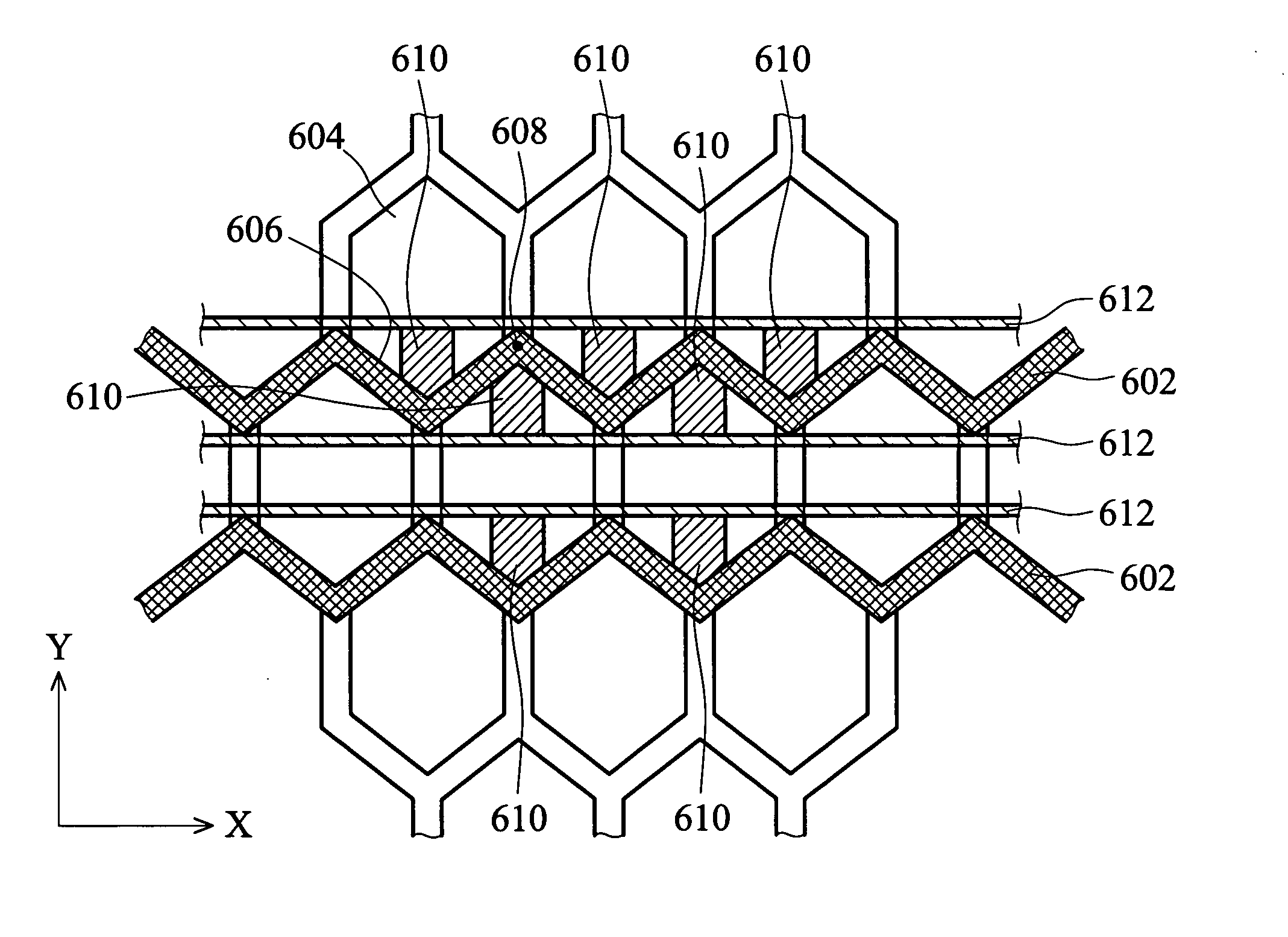
[0043]FIG. 10 is a top view of the PDP of the second embodiment. As shown in FIG. 10, a plurality of ribs are disposed on a rear substrate to form diamond shaped discharge spaces 150 in a delta configuration. Consequently, red non-equilateral hexagonal, green non-equilateral hexagonal and blue non-equilateral hexagonal discharge spaces are formed in a delta configuration. In the preferred embodiment, each rib has two layers with different color. The top layer of the ribs is black to enhance contrast and the bottom layer is white to increase luminance. The preferable height of each rib is 100 μm˜180 μm.
[0044] A front substrate is disposed over a rear substrate. A plurality of bus electrodes 152 are disposed on the front substrate extending in direction X, passing the top region and the down region of the corresponding diamond shaped discharge space 150. The bus electrodes 152 can be arranged in lines and parallel to each other. Each bus electrode 152 includes a plurality of extendin...
third embodiment
[0050]FIG. 14 is a top view of the PDP of the third embodiment. As shown in FIG. 10, a plurality of ribs 560 are disposed on a rear substrate to form cross discharge spaces 552 in a delta configuration 554. Consequently, red cross discharge space 556, green cross discharge space 558 and blue cross discharge space 560 are formed in a delta configuration 554. In the preferable embodiment, each rib 560 has two layers with different color. The top layer of the rib 560 is black to enhance contrast and the bottom layer is white to increase luminance. The preferable height of each rib 560 is 100 μm˜180 μm.
[0051] A front substrate is disposed over a rear substrate. A plurality of bus electrodes 562 are disposed on the front substrate, extending in direction X and passing the top region and the down region of the corresponding cross discharge space 558. Each bus electrode 562 can be arranged in a line shape and parallel to each other. The bus electrodes 562 include a plurality of extending ...
PUM
 Abstract
Description
Claims
Application Information