Image-projecting apparatus

a projecting apparatus and image technology, applied in the direction of printers, cameras, instruments, etc., can solve the problems of unnecessarily erroneous detecting operations, increased costs, and no technology to improve af accuracy, so as to achieve satisfactory af accuracy

Inactive Publication Date: 2005-05-05
CANON KK
View PDF6 Cites 24 Cited by
  • Summary
  • Abstract
  • Description
  • Claims
  • Application Information

AI Technical Summary

Benefits of technology

[0015] It is therefore an object of the present invention to provide an image-projecting apparatus, in which an AF method suitable for

Problems solved by technology

Where projection light of such a projector itself is used for focusing adjustment, processing is performs under the same conditions as advantageous conditions of brightness regardless although disadvantageous brightness for the passive AF, the passive AF method can be performing unnecessarily erroneous detecting operation of a focusing.
The respective technologies do not disclose any technology to improve the AF accuracy, which is suitable for a distance detecting or focusing detecting method used for an image-projecting apparatus such as a liquid crystal projector, etc.
Specifically, as has been proposed in Japanese Patent No. 3272429, in the case where the light emitting output of the light emission unit is increased in auto focusing (AF), in the image-projecting apparatus such as a liquid crystal display, etc., it is necessary to employ a lamp suitable for output control as a lamp for illuminating image-forming elements such as a liquid crystal panel, etc., thus problems occur such

Method used


Image

  • Image-projecting apparatus
  • Image-projecting apparatus
  • Image-projecting apparatus

Examples


embodiment 1

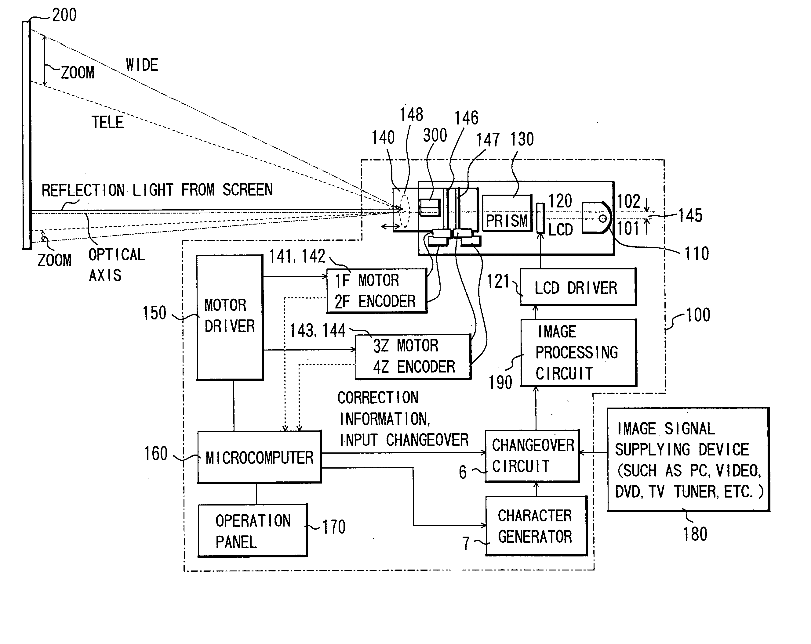
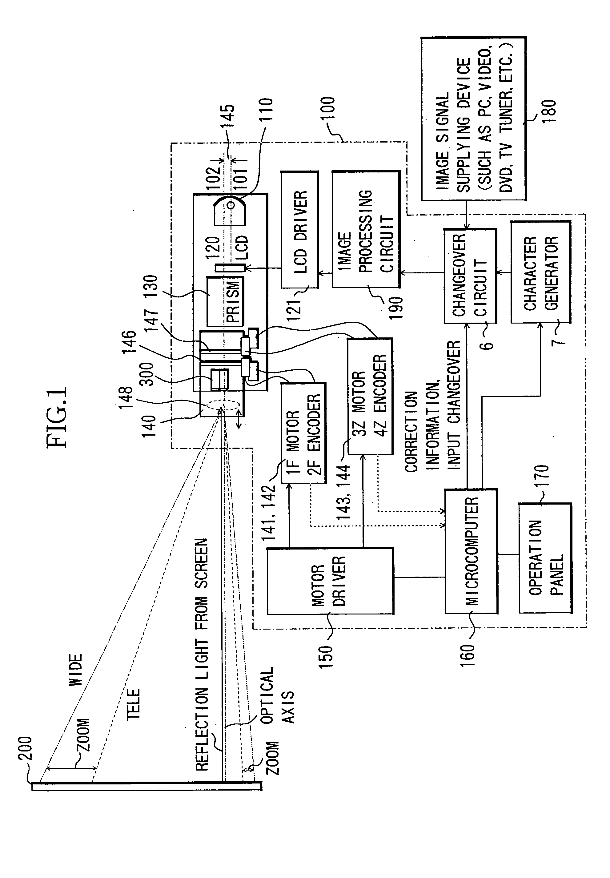
[0032]FIG. 1 shows a structure of 3-plate type liquid crystal projector with an AF (image-projecting apparatus) according to Embodiment 1 of the present invention.

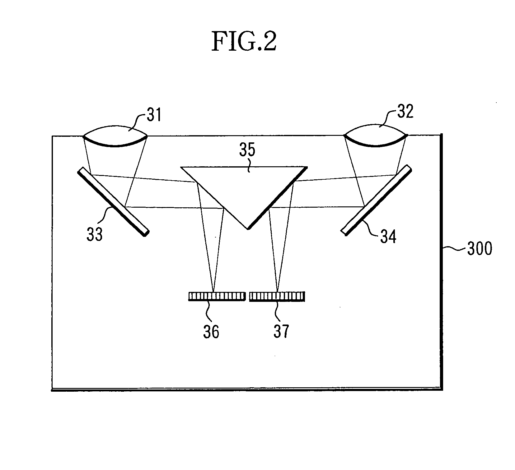
[0033] In FIG. 1, reference numeral 100 denotes a liquid crystal projector. Reference numeral 110 denotes a light source, 120 denotes a transmission type liquid crystal display panel, 130 denotes a cross dichroic prism, 140 denotes a zoom projecting lens (projection optical system), 150 denotes a motor driver, 160 denotes a microcomputer operating as a controller, 170 denotes an operation panel, 180 denotes an image signal supplying device such as a personal computer (PC), a video, a DVD player, a television tuner, etc., 190 denotes an image processing circuit, 200 denotes a screen, and 300 denotes a passive AF sensor including a light-receiving element.

[0034] The basic structure of the projector 100 is a general structure of a 3-plate type liquid crystal projector. That is, three transmission type liquid crystal display...

embodiment 2

[0106]FIG. 7 shows a structure of a 3-plate type liquid crystal projector (image-projecting apparatus) with an AF feature according to Embodiment 2 of the present invention.

[0107] Although, in Embodiment 1, a description was given of a case where a passive AF sensor for distance detection (or focusing detection) is used both as a sensor for detecting the brightness in a projection area and an area other than the projection area, in Embodiment 2, an exclusive brightness detection sensor is employed.

[0108] In FIG. 7, reference numeral 400 denotes a projector, 440 denotes a projecting lens, and 300 denotes a passive AF sensor which is similar to that of Embodiment 1.

[0109] Reference numeral 300a denotes a field of view of the passive AF sensor 300, and reference symbol C denotes an AF chart projected from the projecting lens 440 so that a part thereof is included in the field of view 300a.

[0110] Reference numeral 410 denotes a projection area light-receiving intensity sensor (the f...

embodiment 3

[0113]FIG. 8 shows a structure of a 3-plate type liquid crystal projector (image-projecting apparatus) 400′ with an AF according to Embodiment 3 of the invention.

[0114] In the present embodiment, a sharpness detecting method (a so-called “blurring method” or “contrast detecting method”) is employed as an AF method. A sharpness detection type AF sensor 500 is employed instead of the two-image correlation detection type AF sensor 300 shown in Embodiment 1.

[0115] Reference numeral 500a denotes a field of view of the AF sensor 500. The field of view 500a is established so that it includes a part of the AF chart C projected from the projecting lens 440.

[0116] And, in addition to the AF sensor 500, the light-receiving intensity sensor 410 in the projection area and light-receiving intensity sensor 420 outside the projection area, which are described in Embodiment 2, are employed. Also, elements which are the same as those in Embodiment 2 are given the same reference numerals. Herein, o...


PUM


Abstract

The present invention discloses an image-projecting apparatus which employs an AF (auto-focusing) system suitable for use conditions of the image-projecting apparatus and is capable of securing satisfactory AF accuracy under bright conditions. The image-projecting apparatus comprises a projection optical system which projects light from an image-forming element onto a projection surface, and a detecting system which performs a detecting operation of a distance to the projection surface or a detecting operation of a focusing state of the projection optical system with respect to the projection surface. The detecting system determines a condition of the detecting operation on the basis of the light-receiving intensity level of the light-receiving element which receives reflected light from the projection surface of light projected and performs the detecting operation in accordance with the condition.

Description

BACKGROUND OF THE INVENTION [0001] 1. Field of the Invention [0002] The present invention relates to an image-projecting apparatus such as a liquid crystal projector, etc. In particular, the invention relates to a technology for detecting a focusing state by receiving reflected light when projecting light onto a projection surface, which is a focusing detection technology in the case where the light to be detected is reflection light which derives from image projecting light of the image-projecting apparatus. [0003] 2. Description of Related Art [0004] Conventionally, as an AF (Auto-Focusing) method of a projector, some methods have been known, one of which is an active method which performs auto-focusing based on a principle of triangulation-optical type focusing detection by using infrared light, and another of which is a passive method which reads a contrast of brightness on a screen by means of a pair of light-receiving sensors and driving a lens by obtaining correlation values ...

Claims


Application Information

Patent Timeline
IPC IPC(8): G02B7/28G01B11/00G02F1/13G03B21/00G03B23/02H04N5/74
CPCG03B21/00H04N9/3194H04N9/317G03B21/005
Inventor EGUCHI, MASAHARU
Owner CANON KK
Why Eureka
Try Eureka