Apparatus and method for monitoring optical signal

a technology of optical signal and apparatus, applied in the field of apparatus and method for monitoring optical signal, can solve the problems of low optical signal-to-noise ratio (osnr), degrade system performance, and sensitive technology to optical spatial alignment, and achieve the effect of accurate measuremen

Inactive Publication Date: 2005-05-05
ELECTRONICS & TELECOMM RES INST
View PDF6 Cites 20 Cited by
  • Summary
  • Abstract
  • Description
  • Claims
  • Application Information

AI Technical Summary

Benefits of technology

[0014] By doing so, in a dynamically reconfigurable WDM optical transmission system where ASE noise level vari

Problems solved by technology

The ASE noise lowers the optical signal-to-noise ratio (OSNR) and therefore degrades the performance of the system.
The drawback of this technology is that if power of an optical signal in each signal is assumed to be constant, then even when the ASE noise levels in respective channels in dynamically reconfigurable WDM networks are different, an identical OSNR value is measured in each channel.
In addition, the technology is sensitive to optical spatial alignment.
However, this techno

Method used


Image

  • Apparatus and method for monitoring optical signal
  • Apparatus and method for monitoring optical signal
  • Apparatus and method for monitoring optical signal

Examples


Embodiment Construction

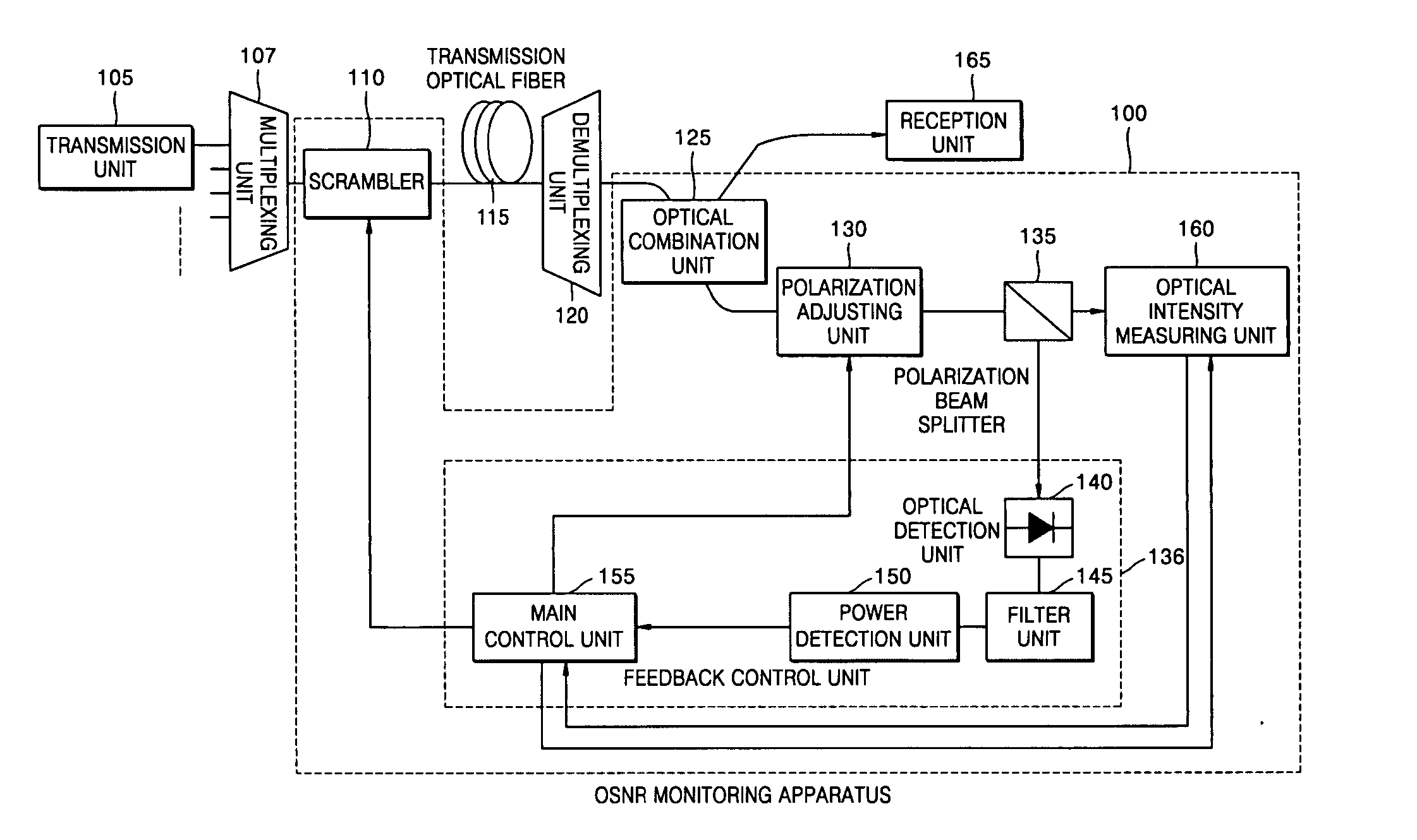
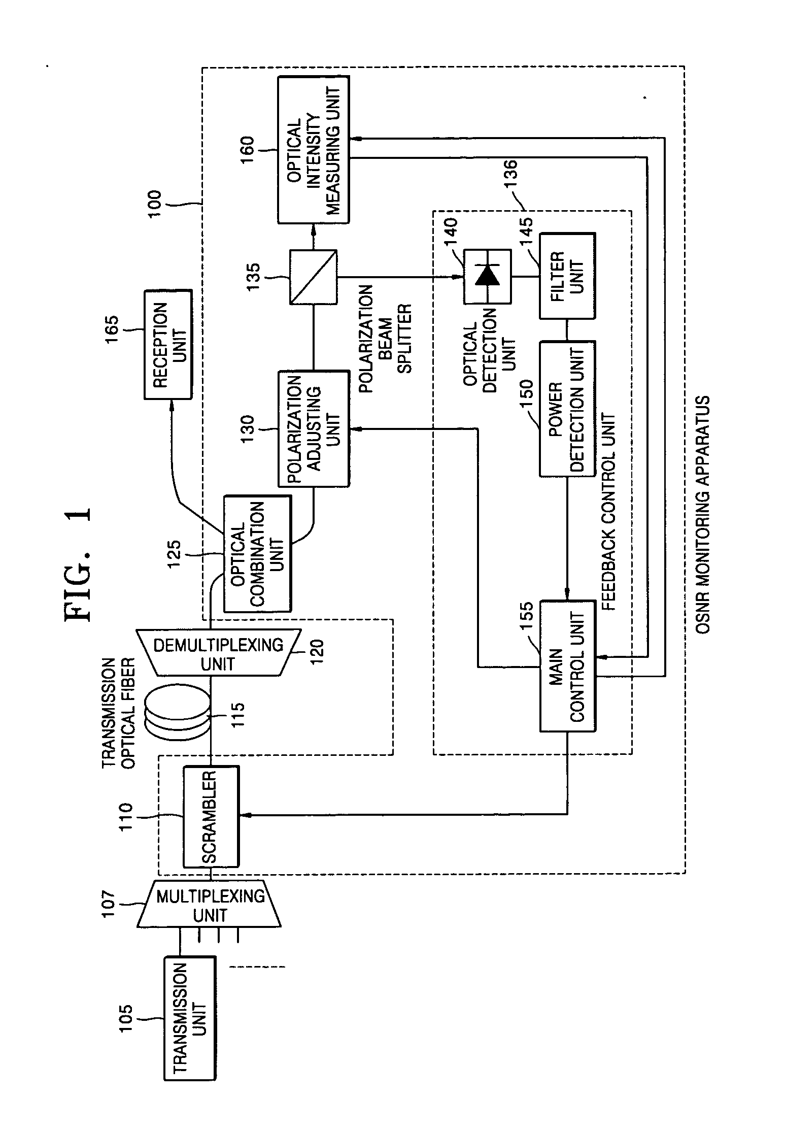
[0022] Referring to FIG. 1, an apparatus for monitoring an optical signal according to the present invention comprises a scrambler 110, an optical combination unit 125, a polarization adjusting unit 130, a polarization beam splitter 135, a feedback control unit 136, and an optical intensity measuring unit 160. The feedback control unit 136 comprises an optical detection unit 140, a filter unit 145, a power detection unit 150 and a main control unit 155. The OSNR monitoring apparatus according to the present invention is connected to a WDM optical transmission system comprising a transmission unit 105, a multiplexing unit 107, transmission optical fiber 115, a demultiplexing unit 120, and a reception unit 165, and monitors an OSNR.

[0023] The transmission unit 105 comprises a plurality of transmission units and each transmission unit 105 outputs an optical signal of a variety of channels. The multiplexing unit 107 multiplexes multi-channel optical signals output from the transmission...


PUM


Abstract

An apparatus and method for monitoring an optical signal are provided. In the apparatus, a polarization adjusting unit converts the state of polarization of an optical signal. A polarization beam splitter splits the optical signal into a first polarization component and a second polarization component perpendicular to each other. An optical intensity measuring unit measures the optical intensity of the first polarization component. A feedback control unit controls the polarization adjusting unit so that the first and second polarization components are aligned to the two axes of the polarization beam splitter. A scrambler scrambles the optical signal input to the transmission optical fiber. According to the apparatus and method, optical signal-to-noise ratio (OSNR) can be measured accurately.

Description

[0001] This application claims priority from Korean Patent Application No. 2003-75799, filed on Oct. 29, 2003, the contents of which are incorporated herein by reference in their entirety. BACKGROUND OF THE INVENTION [0002] 1. Field of the Invention [0003] The present invention relates to an apparatus and method for monitoring an optical signal in a wavelength division multiplexing (WDM) optical transmission system, and more particularly, to an apparatus and method for accurately monitoring an optical signal in an optical transmission system irrespective of polarization mode dispersion (PMD). [0004] 2. Description of the Related Art [0005] In a WDM optical transmission system, various optical amplifiers compensate an optical signal for losses occurring in transmission sections and at the same time amplified spontaneous emission (ASE) noise generating in the amplifiers affects the optical signal. The ASE noise lowers the optical signal-to-noise ratio (OSNR) and therefore degrades the...

Claims


Application Information

Patent Timeline
IPC IPC(8): H04B10/17H04B10/00H04B10/02H04B10/08H04B10/135H04J14/02H04J14/06
CPCH04B10/07953H04J14/06H04J14/02H04B10/532H04B10/07H04B10/2569H04B10/2581
Inventor HAN, KI HOLEE, WANGJOOKO, JE SOO
Owner ELECTRONICS & TELECOMM RES INST
Why Eureka
Try Eureka