Electrical circuit apparatus with fuse access section

a technology of fuse access and circuit equipment, which is applied in the direction of electrical apparatus casings/cabinets/drawers, gaseous cathodes, substation/switching arrangement casings, etc. it can solve the problems of unsuitable prior art fusing and fuse access schemes, size or current capacity of fuse not suitable for these types of fuse arrangements, and internal fuses (with one or more fuses mounted within the confines of a closed housing) are not easily inspected or accessed

Active Publication Date: 2005-05-05
SERVER TECHNOLOGY
View PDF5 Cites 53 Cited by
  • Summary
  • Abstract
  • Description
  • Claims
  • Application Information

AI Technical Summary

Benefits of technology

[0022] In other embodiments, the housing may comprise a power distribution unit (PDU). The PDU may include any of a number of features described in this or the Detailed Description section infra. In combination with an associated or co-integrated equipment rack, the PDU/rack can most preferably provide convenient access to fuses within the

Problems solved by technology

In many other applications, these types of prior art fusing and fuse-access schemes are unsuitable.
In many instances, the size or current capacity of the fuse does not lend itself to these types of fuse arrangements.
These types of internally mounted fuses (with one or more fuses mounted within the confines of a closed housing) are not easily inspected or accessed.
A user of this type of equipment therefore cannot even inspect a fuse, much less gain access to it for removal or replacement, without voiding the warranty.
These types of fuse access problems have long been quite predominant in the case of rack mounted systems in which system components are connected to a power distribution unit (PDU) that supplies power to the components in th

Method used


Image

  • Electrical circuit apparatus with fuse access section
  • Electrical circuit apparatus with fuse access section
  • Electrical circuit apparatus with fuse access section

Examples


Embodiment Construction

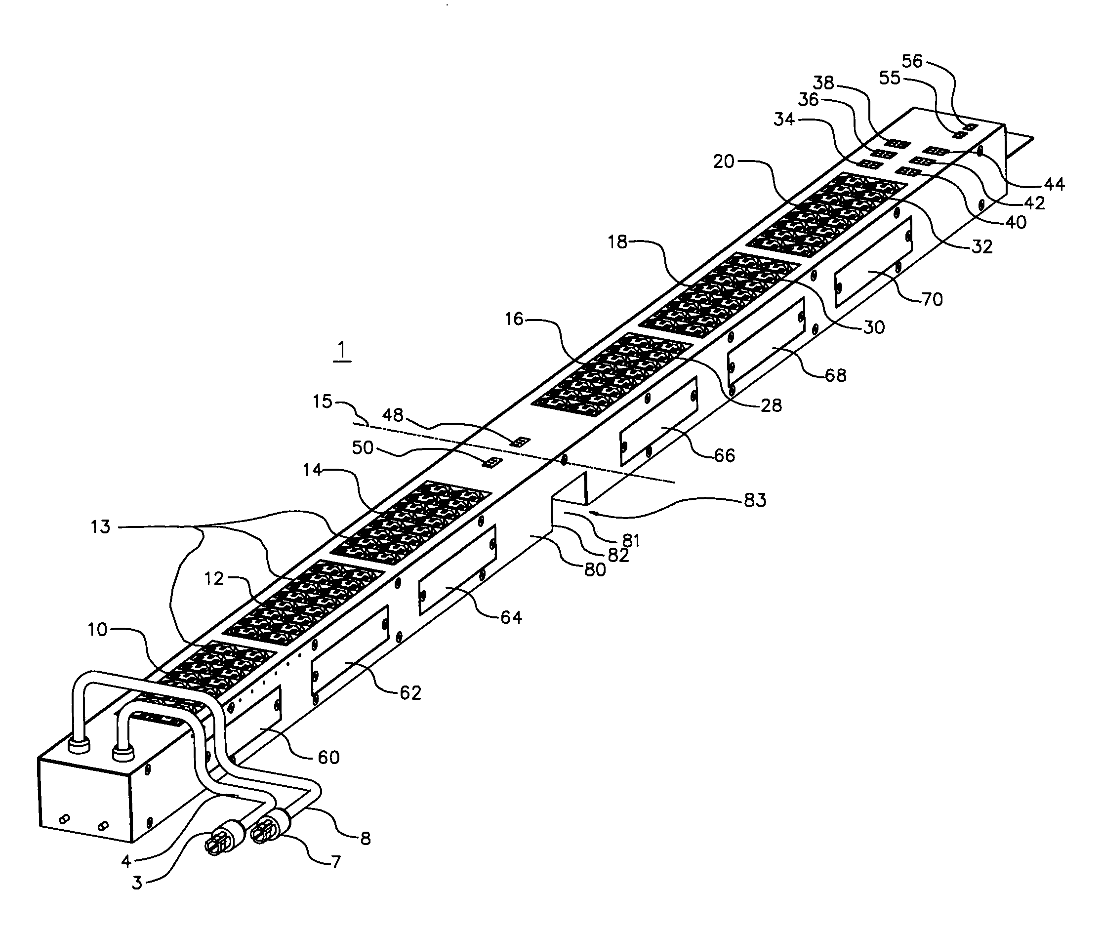
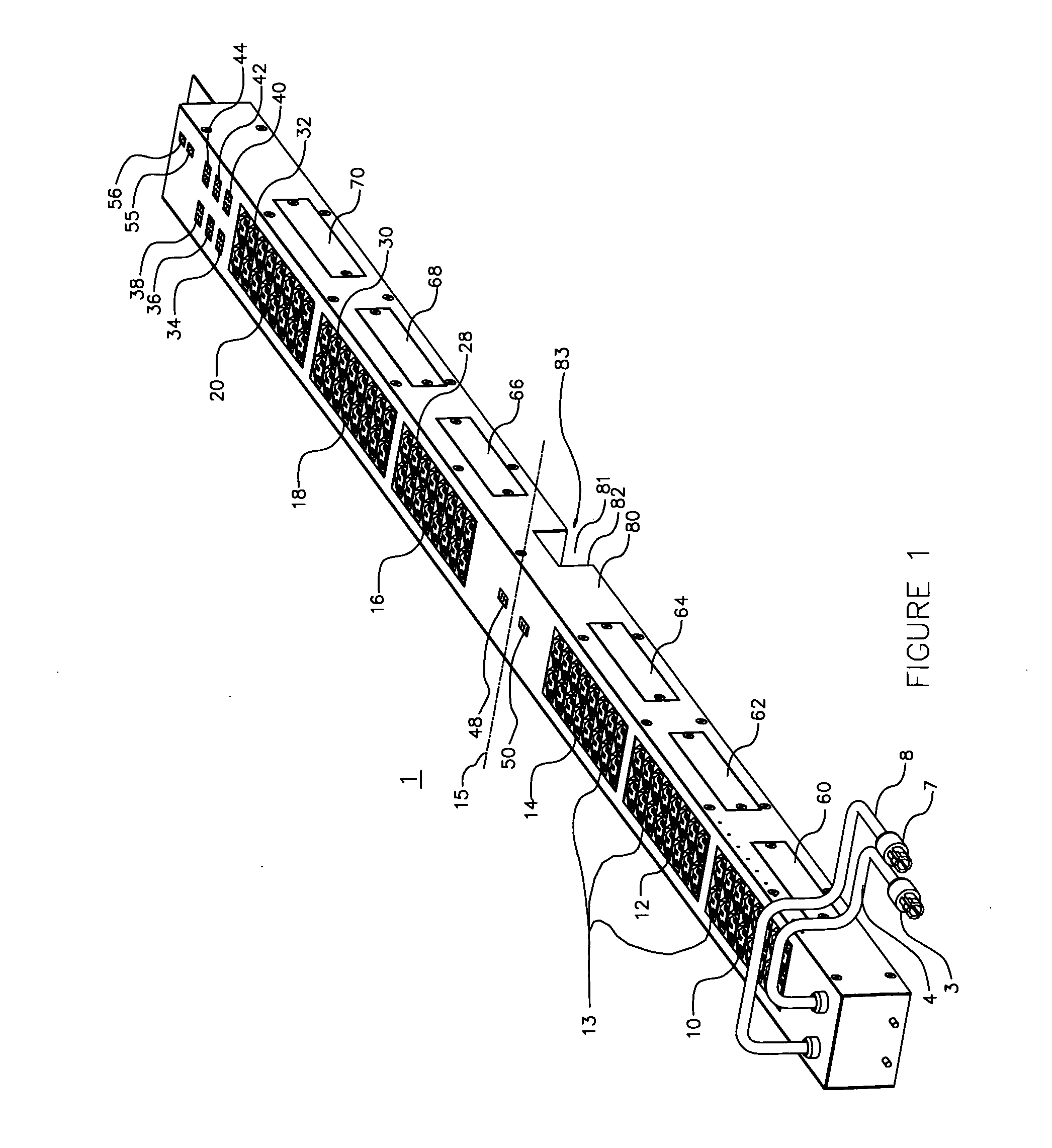
[0046] With reference now to FIG. 1, an electrical power distribution unit (PDU) 1 is adapted to receive one or more polyphase power inputs and to provide a plurality of single-phase power outputs. In the embodiment of FIGS. 20-22, the PDU 1 may be included in a rack mounted data center. Many other different forms of apparatus other than a PDU may be provided in accordance with the present invention. The context of a PDU is provided as a preferred example.

[0047] It should be noted that this specification employs spatially orienting terms to explain relative locations. In order to provide orientation with respect to the housing 2, the vertical dimension is also referred to as the longitudinal dimension. The horizontal dimension across the front panel 9 is the lateral dimension. The third dimension perpendicular to the surface of the front panel 9 is the transverse dimension.

[0048] With continuing reference to FIG. 1, a first three-phase plug 3 is connected to a three-phase alternat...


PUM


Abstract

An electrical apparatus has an elongated housing with fuses located therein. Windows are provided in the housing to close apertures in registration with fuse locations to allow access to fuses by removing the window. Fuses may be carried on a circuit card removably engageable with a terminal block secured to a wall within the housing. A fuse compartment cover is removably secured to the housing. The window comprises a fuse condition indicator to allow determination of the condition of the fuse (i.e. blown or not blown) without having to open the window. Additionally, powered indicators such as LEDs visible through the windows may indicate the state of fuses. The housing may comprise a power distribution unit and may be rack mounted or mounted to a wall of a rack assembly. The windows are located on the housing to be removable free of engagement with the assembly. In various embodiments, the windows may be included in a different one of the walls so that the windows will be unobstructed when the housing is in one of a number of orientations. The fuse compartment may be opened without removing the unit from the rack.

Description

CROSS REFERENCE TO RELATED APPLICATIONS [0001] This patent application claims the benefit of priority of U.S. provisional patent applications (i) Ser. No. 60 / 516,671, filed Oct. 30, 2003, entitled “Power Distribution and Fuse Apparatus,” and (ii) Ser. No. 60 / 525,780, filed Nov. 28, 2003, entitled “Power Distribution and Fuse Apparatus-B,” both of which U.S. provisional patent applications are hereby incorporated herein by reference in their entirety.FIELD OF THE INVENTION [0002] The present invention relates to fused electrical apparatus having a housing allowing access to a fuse compartment and more particularly, in one preferred form, to a rack associated or rack-mountable power distribution apparatus having accessible fuse compartments. BACKGROUND [0003] Fuses are widely used in electrical equipment connected in series to protect conductors and components from damage due to high current levels (“overcurrent”). Typically, a fuse consists of a fusible link installed in a circuit. W...

Claims


Application Information

Patent Timeline
IPC IPC(8): H01H85/02H01H85/20H01H85/30H01H85/32
CPCH01H85/0241H01H85/32H01H85/30
Inventor EWING, CARREL W.CLEVELAND, ANDREW J.
Owner SERVER TECHNOLOGY
Why Eureka
Try Eureka