Direct link relay in a wireless network

a direct link relay and wireless network technology, applied in the field of wireless network power management, can solve the problem of limited maximum transmission rate supportable between wireless devices, and achieve the effects of cost saving, transparent operation, and cost saving

Active Publication Date: 2005-05-05
INTELLECTUAL VENTURES I LLC
View PDF99 Cites 127 Cited by
  • Summary
  • Abstract
  • Description
  • Claims
  • Application Information

AI Technical Summary

Benefits of technology

[0009] The present invention mitigates or solves the above-identified limitations in known solutions, as well as other unspecified deficiencies in known solutions. A number of ...

Problems solved by technology

However, the maximum transmission rate supportable between wireless devices may be limited for any number of reasons, such as, for example, th...

Method used


Image

  • Direct link relay in a wireless network
  • Direct link relay in a wireless network
  • Direct link relay in a wireless network

Examples


Embodiment Construction

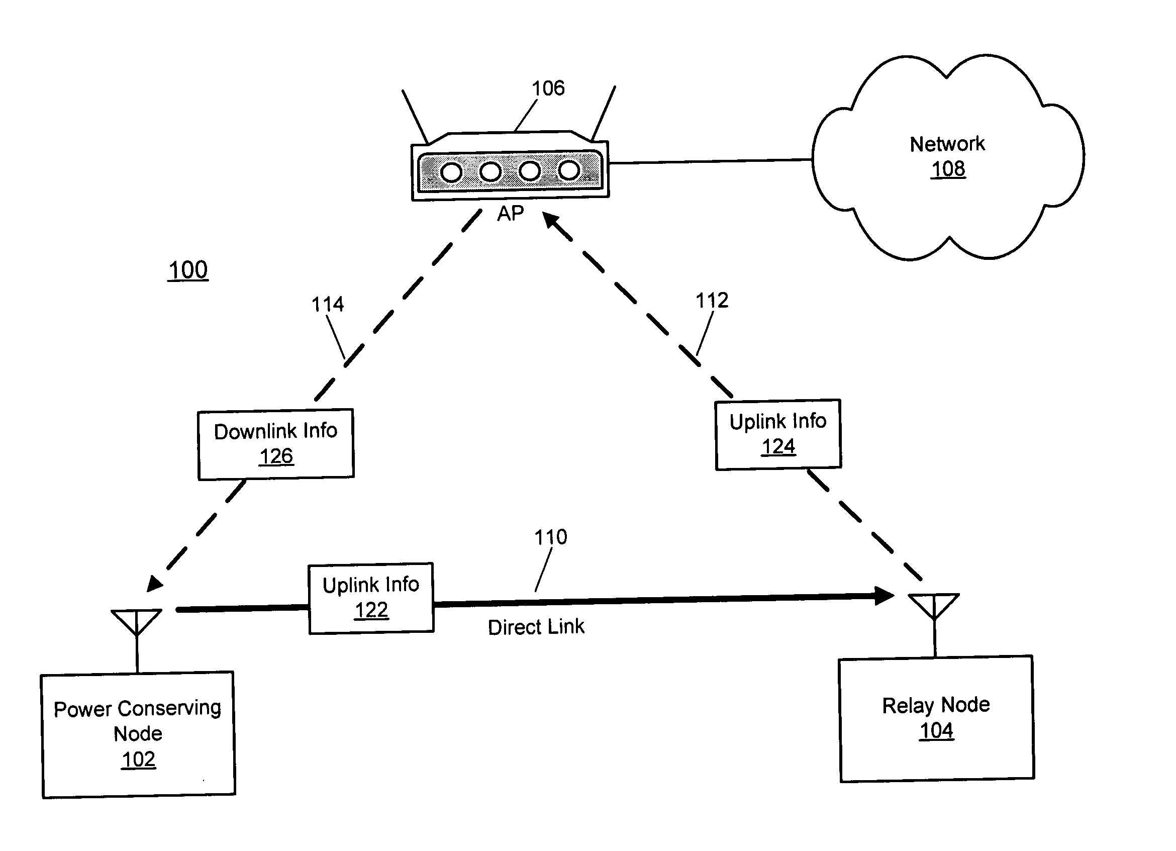
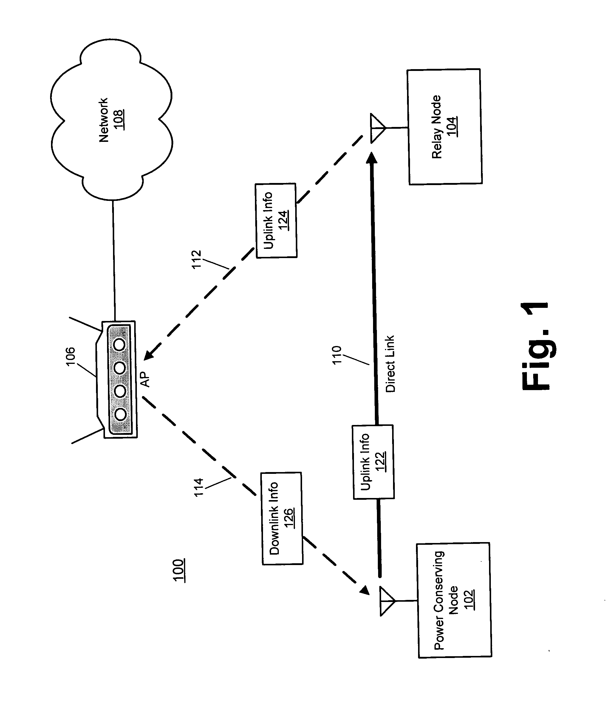
[0021] The following description is intended to convey a thorough understanding of the present invention by providing a number of specific embodiments and details involving the minimization of the transmit power used by a wireless device by relaying frames to an access point via another wireless device. It is understood, however, that the present invention is not limited to these specific embodiments and details, which are exemplary only. It is further understood that one possessing ordinary skill in the art, in light of known systems and methods, would appreciate the use of the invention for its intended purposes and benefits in any number of alternative embodiments, depending upon specific design and other needs.

[0022] For ease of illustration, the various techniques of the present invention are discussed below in the context of IEEE 802.11-based wireless networking. However, those skilled in the art, using the teachings provided herein, may advantageously implement the disclosed...


PUM


Abstract

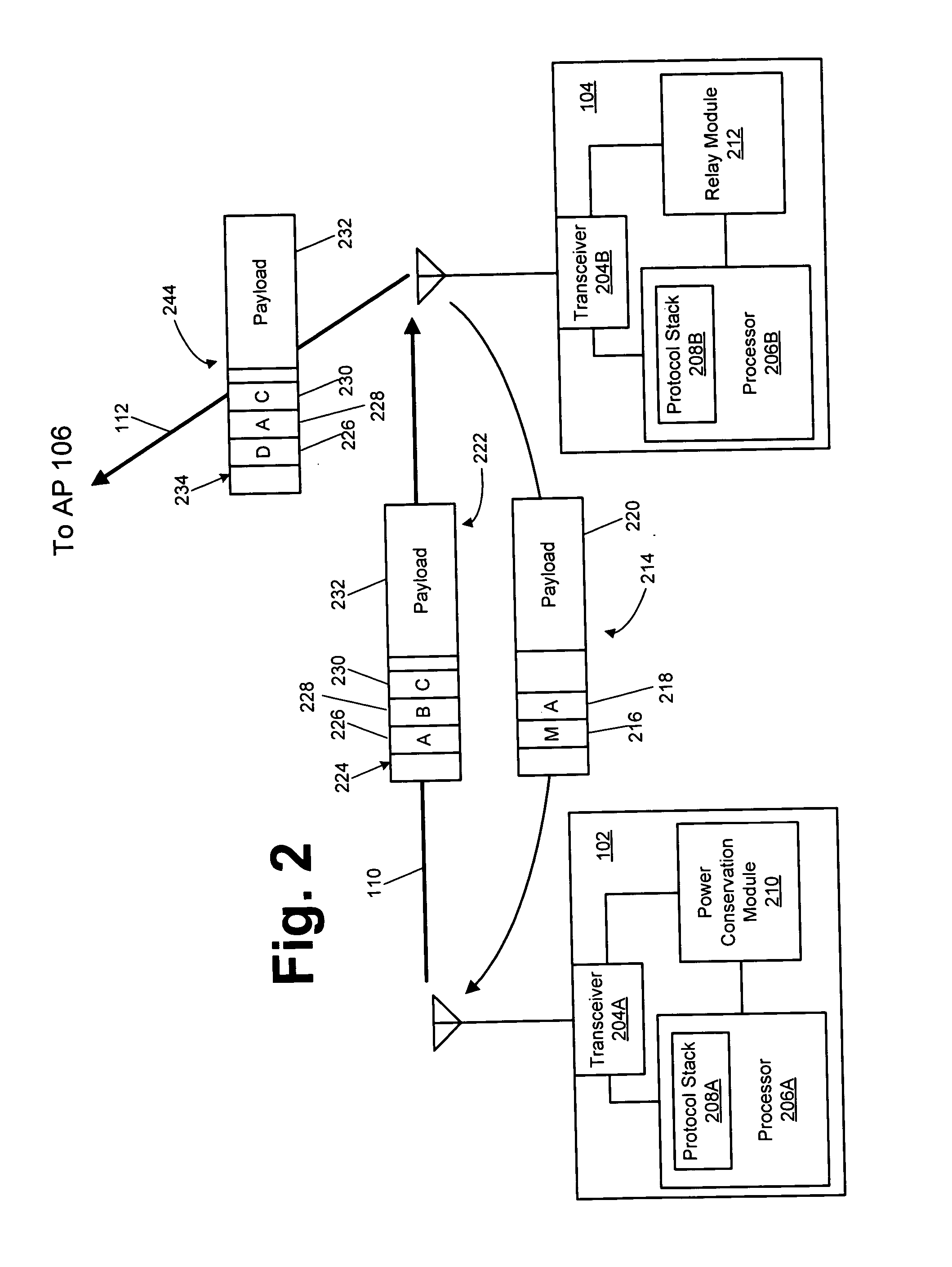
Disclosed herein are exemplary techniques for power conservation in a wireless network. A wireless device identifies another wireless device suitable to act as a relay node. Uplink information is transmitted to the other wireless device, which is in turn relayed to an access point for transmission to its destination. Downlink information may be transmitted directly from the access point to the wireless device. The use of a relay node may reduce transmit power consumption as the relay node may be closer to, or support a higher transmit rate, than the access point with which the wireless device is associated.

Description

CROSS-REFERENCE TO RELATED APPLICATIONS [0001] The present invention claims benefit of U.S. Patent Application No. 60 / 515,701 (Client Reference: GV 297; Attorney Docket No.: 56162.000497) filed Oct. 31, 2003 and entitled “Location Awareness in Wireless Networks,” the entirety of which is incorporated by reference herein. [0002] U.S. patent application Ser. No. ______ (Client Reference: GV 317; Attorney Docket No.: 56162.000517) filed concurrently herewith and entitled “Event-Based Multichannel Direct Link,” U.S. patent application Ser. No. ______ (Client Reference: GV 319; Attorney Docket No.: 56162.000519) filed concurrently herewith and entitled “Piggyback Ack Link Margin Frames,” U.S. patent application Ser. No. ______ (Client Reference: GV 320; Attorney Docket No.: 56162.000520) filed concurrently herewith and entitled “Time-Scheduled Multichannel Direct Link,” all claiming benefit of U.S. Provisional Application No. 60 / 515,701 (Client Reference: GV 297; Attorney Docket No.: 561...

Claims


Application Information

Patent Timeline
IPC IPC(8): H04B7/005H04L12/28
CPCH04W40/10H04W52/04H04W52/48H04W88/04H04W52/0258Y02D30/70
Inventor WENTINK, MENZO
Owner INTELLECTUAL VENTURES I LLC
Why Eureka
Try Eureka