Plug-type device for retrieving spinal column under treatment

Inactive Publication Date: 2005-05-05
A SPINE HLDG FROUP CORP +1
View PDF4 Cites 181 Cited by
  • Summary
  • Abstract
  • Description
  • Claims
  • Application Information

AI Technical Summary

Benefits of technology

[0014] Preferably, the fastening hole has a longitudinal axis parallel to a longitudinal axis of the interconnecting hole. More preferably, the plug has two arcuate claws at one side and a round recess on a slant surface at another side thereof, wherein the arcuate claws and the receiving hole together form a mechanism for grasping the retrieval rod in the receiving hole, and the round recess on the slant surface increases the contact area between the plug and the C-shaped ring.
[0015] The p

Problems solved by technology

Consequently, the conventional spinal retrieval devices c

Method used


Image

  • Plug-type device for retrieving spinal column under treatment
  • Plug-type device for retrieving spinal column under treatment
  • Plug-type device for retrieving spinal column under treatment

Examples


Embodiment Construction

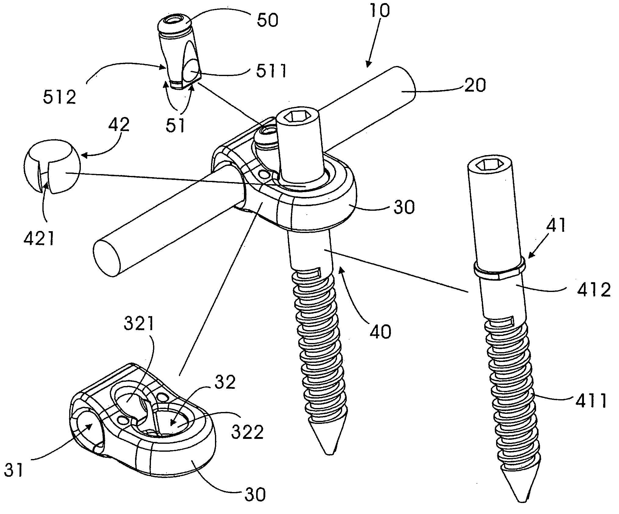
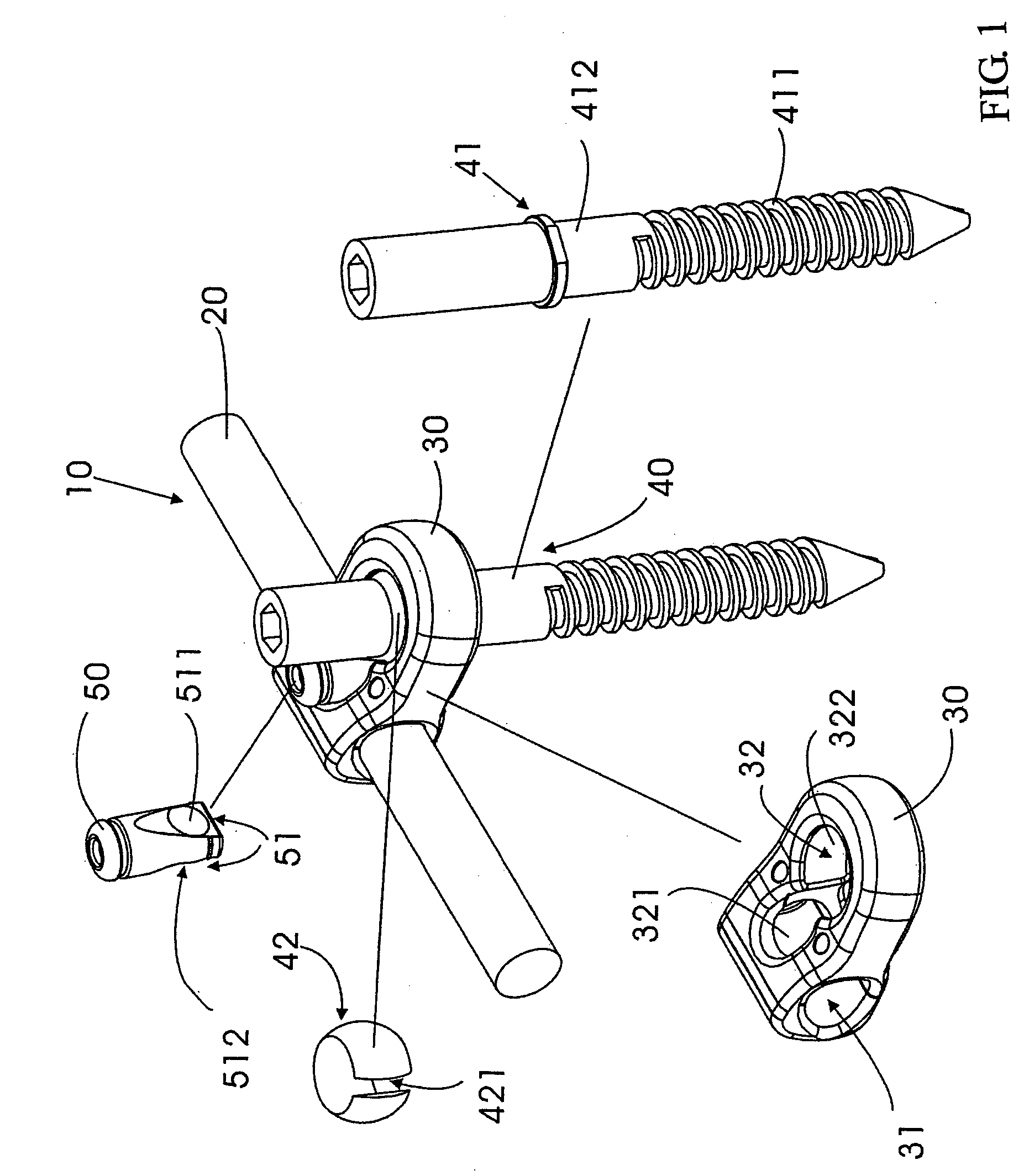
[0021] A plug-type spinal retrieving device 10 constructed according to one of the preferred embodiments of the present invention is shown in FIG. 1, which includes a retrieval rod 20; a fastening screw assembly 40 including a fastening screw 41 and a C-shaped ring 42; a plug 50; and a fixation seat 30 having a receiving hole 31 in which the retrieval rod 20 is slidably received, a fastening hole 32 having a concave wall 322 in which the C-shaped ring 42 is rotatably received, and an interconnecting hole 321 through which the receiving hole 31 communicates with the fastening hole 32.

[0022] The fastening screw 41 has a threaded portion 411 and an upper portion with a flange between the two portions. The C-shaped ring 42 is put on the upper portion and retained by the flange of the fastening screw 41. The C-shaped ring 42 has a slot 421 and a convex outer surface corresponding to the concave wall 322 of the fastening hole 32, so that the C-shaped ring 42 can be compressed and rotatab...


PUM


Abstract

A plug-type spinal retrieving device includes a retrieval rod; a fastening screw assembly including a fastening screw and a C-shaped ring having a convex outer surface; a plug; and a fixation seat having a receiving hole in which the retrieval rod is slidably received, a fastening hole having a concave wall in which the C-shaped ring is rotatably received, and an interconnecting hole through which the receiving hole communicates with the fastening hole. The C-shaped ring is mounted on the fastening screw, so that the fastening screw is grasped by the C-shaped ring, when the C-shaped ring is received in the fastening hole of the fixation seat. The C-shaped ring and the retrieval rod are immobilized in the fastening hole and the receiving hole of the fixation seat by inserting the plug into the interconnecting hole.

Description

FIELD OF THE INVENTION [0001] The present invention relates generally to a spinal surgical care device, and more particularly to a rotary device for retrieving spine column under treatment. BACKGROUND OF THE INVENTION [0002] The conventional spinal retrieval devices use complicated locking mechanisms to secure a rod with a spinal screw or hook body such as those disclosed in U.S. Pat. Nos. 5,147,359 and 6,602,253. [0003] Consequently, the conventional spinal retrieval devices complicate the spinal surgery and prolong the surgery time. SUMMARY OF THE INVENTION [0004] A primary objective of the present invention is to provide a rotary device for fixing spinal column under treatment without the drawbacks of the prior art. [0005] A plug-type spinal retrieving device constructed according to the present invention comprises: [0006] a retrieval rod; [0007] a fastening screw assembly comprising a fastening screw and a C-shaped ring having a convex outer surface; [0008] a plug; and [0009] a ...

Claims


Application Information

Patent Timeline
IPC IPC(8): A61B17/70
CPCA61B17/7041A61B17/7037
Inventor LIN, CHIH-I
Owner A SPINE HLDG FROUP CORP
Why Eureka
Try Eureka