Apparatus for jitter testing an IC

a technology of integrated circuits and apparatuses, applied in the direction of electric unknown time interval measurement, recording information storage, setting time indication, etc., can solve the problems of random jitter, data signal jitter relative to clock signal edges, data signal jitter relative to receiving ic edges, etc., to minimize delays and noise

Inactive Publication Date: 2005-05-05
CREDENCE SYSTEMS
View PDF63 Cites 40 Cited by
  • Summary
  • Abstract
  • Description
  • Claims
  • Application Information

AI Technical Summary

Benefits of technology

[0018] The receiver circuit, the transmitter circuit and the measurement circuit are all implemented on the same IC in order to keep signal paths interconnecting them to one another and to the DUT short, thereby minimizing delays and noise in those signal paths. Since the communications between the IC and the processing circuit are not as sensitive to noise and delays, the processing circuit can be external to the IC.

Problems solved by technology

Random jitter arises from random noise in the transmitting IC or in the signal path conveying the signal to the receiving IC.
In a system where the transmitting IC sends a clock signal to the receiving IC, noise in the clock signal path can also cause the receiving IC to perceive the data signal to be jittery relative to clock signal edges.
In a receiving IC employing a clock recovery system to generate a local clock signal, feedback errors or noise in the clock recovery system can cause jitter in the clock signal, thereby causing the data signal to appear jittery relative to clock signal edges.
Random jitter renders the timing of each data signal edge somewhat non-deterministic in that is not possible for the receiving IC to predict the amount of timing error in any individual signal edge arising from random noise.
Since a receiving IC periodically samples a digital signal between transitions to determine the data sequence it represents, it can tolerate some amount of jitter, but when a digital signal is too jittery, the receiving IC not be able to correctly determine each successive state of the digital signal from the samples it acquires because it will sometimes sample the signal to soon or too late.
A receiving IC can also tolerate some amount of noise-induced variation in the voltage of its signal logic levels, but when the variation becomes too large, it will not be able to correctly determine the logic level represented by each sample because the signal may sometimes may fail to be on the correct side of the midpoint voltage at the moment the receiver samples it.
However while a tester channel can accurately adjust timing of DUT input signal edges, in many applications a typical tester channel cannot control the timing of edges of a DUT input signal with sufficient resolution to produce the desired jitter pattern.

Method used


Image

  • Apparatus for jitter testing an IC
  • Apparatus for jitter testing an IC
  • Apparatus for jitter testing an IC

Examples


Embodiment Construction

[0039] The invention relates in general to automated test equipment, and in particular to a system for testing an integrated circuit for its tolerance to jitter in its input signals and for measuring the amount of jitter in its output signals. While the specification describes in detail an exemplary embodiment of the invention considered a best mode of practicing the invention, those of skill in the art will appreciate that other modes of practicing the invention are possible.

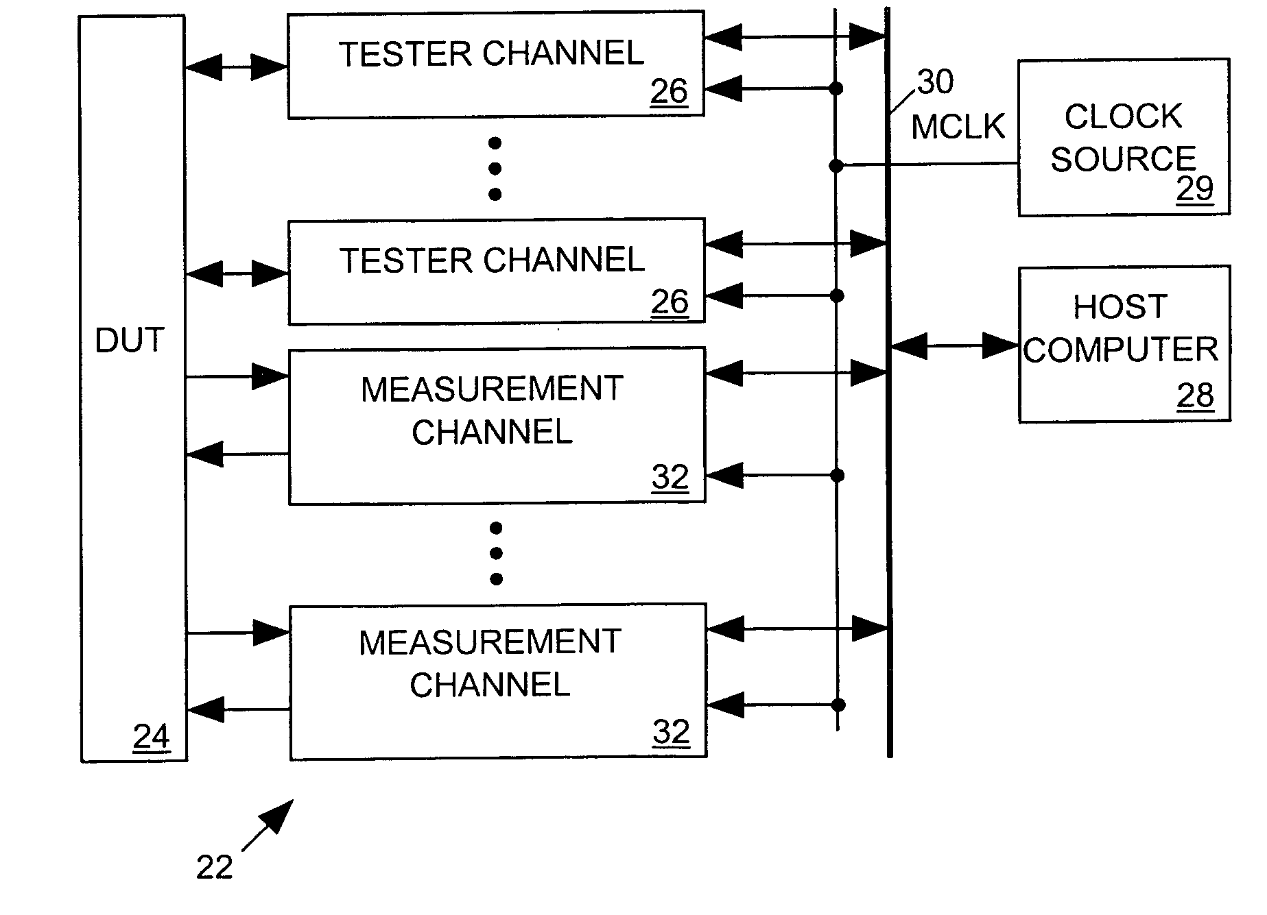
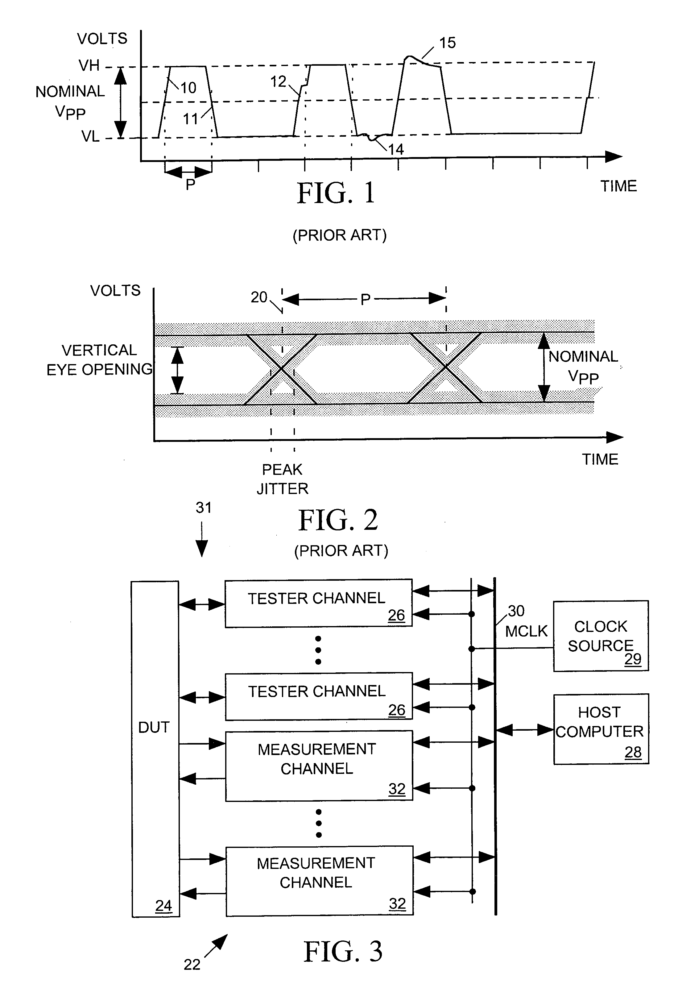
[0040]FIG. 3 depicts an integrated circuit (IC) tester 22 incorporating the present invention, including a set of conventional tester channels 26, each connected to a separate pin of an IC device under test (DUT) 24 through signal paths 31. Programmed by instructions supplied from a host computer 28 via a bus 30 and synchronized to a master clock signal MCLK produced by a clock source 29, each tester channel 26 may either transmit an input signal having a particular pattern to DUT 24 or monitor an output signa...


PUM


Abstract

An integrated circuit tester channel includes an integrated circuit (IC) for adding a programmably controlled amount of jitter to a digital test signal to produce a DUT input signal having a precisely controlled jitter pattern. The IC also measures periods between selected edges of the same or different ones of the DUT output signal, the DUT input signal, and a reference clock signal. Additionally, when the DUT input and output signals convey repetitive patterns, the IC can measure the voltage of the DUT input out output signal as selected points within the pattern by comparing it to an adjustable reference voltage. Processing circuits external to the IC program the IC to provide a specified amount of jitter to the test signal, control the measurements carried out by the measurement circuit, and process measurement data to determine the amount of jitter and other characteristics of the DUT output signal, and to calibrate the jitter in the DUT input signal.

Description

CROSS-REFERENCE TO RELATED APPLICATIONS [0001] This application is a continuation-in-part of U.S. patent application Ser. No. 10 / 646,957 filed Aug. 21, 2003. [0002] This application is also a continuation-in-part of U.S. patent application Ser. No. 10 / 954,572 filed Sep. 30, 2004.BACKGROUND OF THE INVENTION [0003] 1. Field of the Invention [0004] The invention relates in general to an apparatus for testing an integrated circuit (IC) and in particular to an apparatus for testing the ability of an IC to accommodate jittery input signals and for measuring the amount of jitter in its output signals. [0005] 2. Description of Related Art [0006] Digital integrated circuits (ICs) communicate through digital data signals, and when a transmitting IC transmits a digital data signal to a receiving IC, it typically synchronizes state changes in the digital data signal to leading (or trailing) edges of a periodic clock signal so that they occur at predictable times. To produce a data sequence repr...

Claims


Application Information

Patent Timeline
Patent Type & Authority Applications(United States)
IPC IPC(8): G01R29/26G01R31/28G01R31/317G01R31/3185G01R31/319
CPCG01R29/26G01R31/2841G01R31/31709G01R31/31922G01R31/318533G01R31/3191G01R31/31715
Inventor FRISCH, ARNOLD M.ALMY, THOMAS ARTHUR
Owner CREDENCE SYSTEMS
Why Eureka
Try Eureka