Apparatus and method for steering a vehicle

Inactive Publication Date: 2005-05-12
STEERING SOLUTIONS IP HLDG +1
View PDF36 Cites 17 Cited by
  • Summary
  • Abstract
  • Description
  • Claims
  • Application Information

AI Technical Summary

Benefits of technology

[0011] In one exemplary embodiment, a steering system for a vehicle may include a steering wheel being positioned for manipulation by a vehicle operator, a steering mechanism for transmitting a steering operation of the steering wheel to vary the angular configuration of at least one wheel of the vehicle, a power assist mechanism for pro

Problems solved by technology

With electrically actuated or electrically assisted steering systems there is a significant servo mechanism design challenge associated with the need to maintain proper kinematical constraint, while at the same time, providing reasonable insulation from the

Method used


Image

  • Apparatus and method for steering a vehicle
  • Apparatus and method for steering a vehicle
  • Apparatus and method for steering a vehicle

Examples


Embodiment Construction

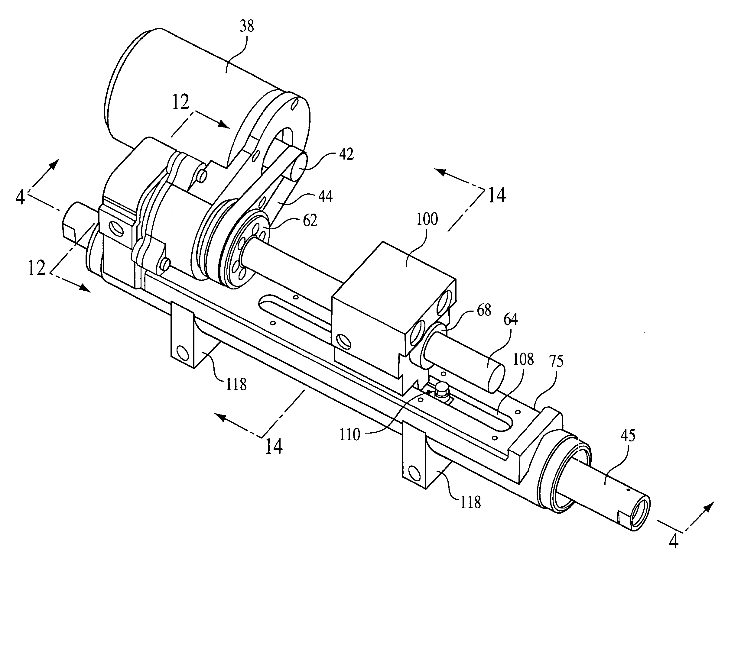
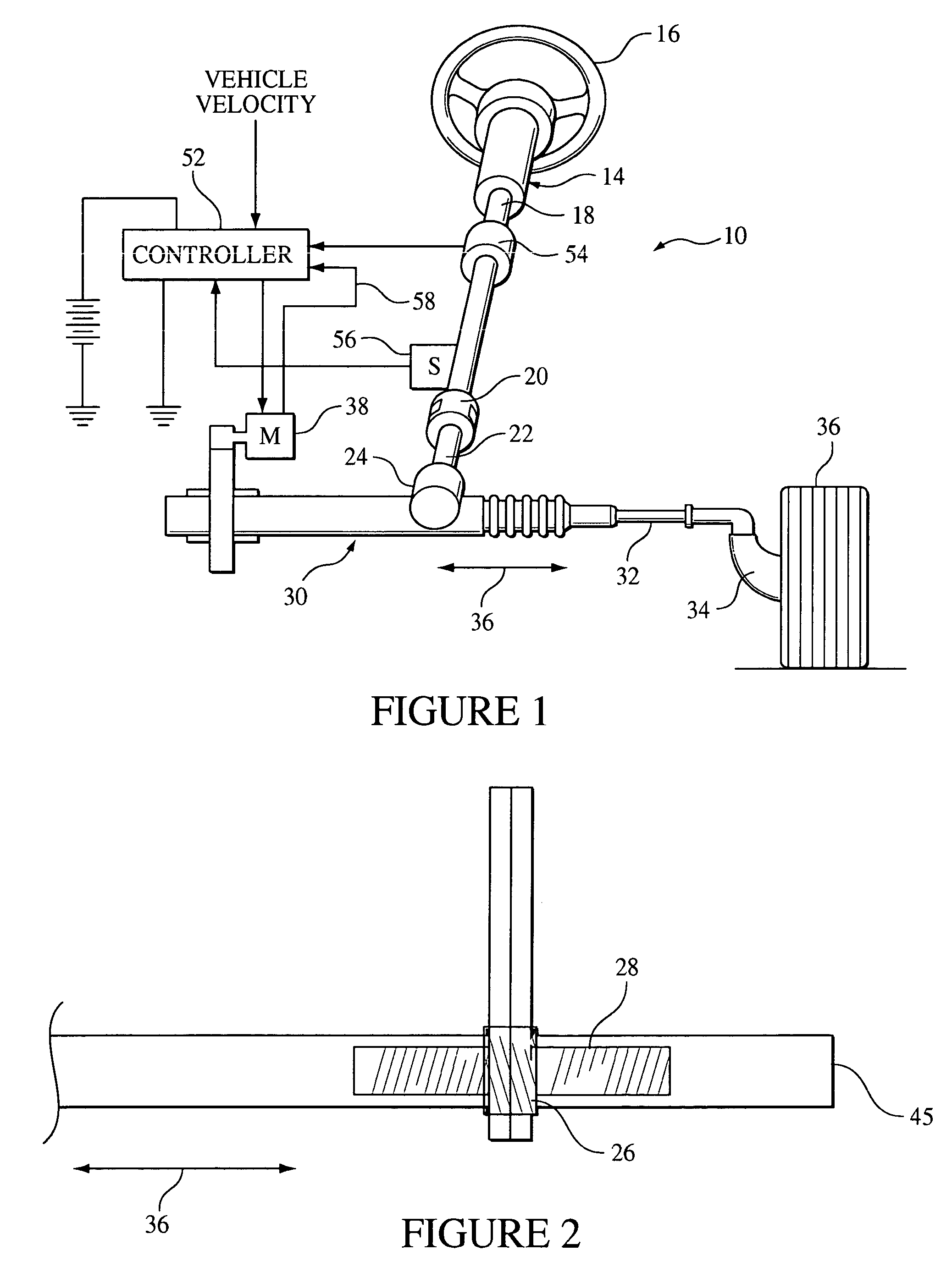
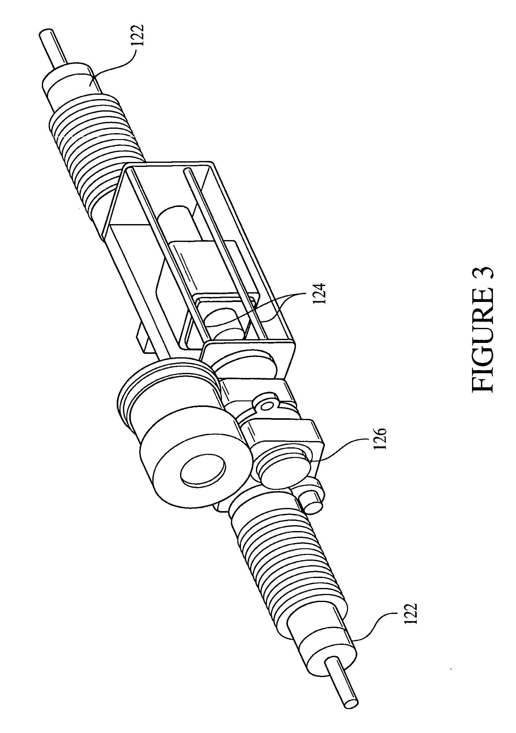
[0049] Aspects of these embodiments relate generally to an apparatus and method for steering a vehicle, and more specifically to a rack-independent actuator. A steering system for a vehicle may include a rack-independent actuator. The rack-independent actuator may include component parts that isolate from undesirable loads by two universal joints that may isolate mechanical components of the actuator from transient loads that may be encountered by the rack or rack housing.

[0050] The system may be powered by a rotary type electric motor. The motor has speed reducers and rotary-to-linear actuators to achieve feasible size and linear actuation. The actuation-unit is decoupled from the directionally unwanted loads by providing universal joints (or an equivalent degree of freedoms) at either end. One universal joint is mounted to the housing that holds the motor rotary-to-rotary speed reducer and the movable shaft of the linear-to-rotary actuator, and the other is mounted to a member th...


PUM


Abstract

A steering system for a vehicle may include a load displacement system allowing transient loads of the steering mechanism to be displaced. The steering system may also include a first coupling mechanism coupling an electric motor to a rack housing, and a second coupling mechanism coupling a ball nut to a rack. A method for providing an actuation force to a rack of a vehicle includes isolating non-axial loads from an electric motor of a steering system and isolating non-axial loads from a linearly actuatable member of a rotary-to-linear conversion device in the steering system. An actuator for a steering system may include a rotary to linear actuator, a movable linear section, and an interface between the rotary to linear actuator and the linear section. The interface may include one or more cylindrical joints, revolute joints, compliant members, or a block on a plane wherein the total degrees of freedom for the system including the rotary to linear actuator, rack, and interface may be one, while the interface may be limited to three degrees of freedom.

Description

CROSS REFERENCE TO RELATED APPLICATIONS [0001] This is a continuation-in-part of U.S. Patent Application Ser. No. 10 / 765,731, filed Jan. 26, 2004, which is a continuation application of U.S. patent application Ser. No. 10 / 262,751 (now U.S. Pat. No. 6,705,423), which is a divisional of U.S. patent application Ser. No. 09 / 920,181, filed Aug. 1, 2001 (now U.S. Pat. No. 6,488,115) which is related to U.S. patent application, Ser. No. 09 / 664,850, filed Sep. 19, 2000, wherein the contents of all of the above listed applications and patents are incorporated in their entirety herein by reference. [0002] This application also claims priority to U.S. Provisional Patent Application 60 / 540,643 filed on Jan. 30, 2004, wherein the contents are incorporated in its entirety herein by reference. [0003] This application is also related to U.S. patent application, Ser. No. 09 / 650,869, filed Aug. 30, 2000, the contents of which are incorporated herein by reference thereto. [0004] This application is al...

Claims


Application Information

Patent Timeline
IPC IPC(8): B62D5/04
CPCB62D5/0421B62D5/0424F16H2025/2096B62D5/0445B62D5/0448B62D5/0427
Inventor OZSOYLU, SUAT ALIJIMKOSKI, MATTHEW HARVEYPYRETT, MICHAEL RICHARDFERIEND, WILLIAM F.
Owner STEERING SOLUTIONS IP HLDG
Why Eureka
Try Eureka