Method and system for electric discharge machining insulating material or high resistance material

a technology of insulating material and high resistance material, which is applied in the direction of manufacturing tools, electric circuits, welding apparatuses, etc., can solve the problems of inability to stably perform machining, inability to use above conventional electric discharge techniques on a full scale, and inability to achieve high resistance materials, improve the quality of the machine face, and stabilize the machining of the workpi

Inactive Publication Date: 2005-05-12
MITSUBISHI ELECTRIC CORP +1
View PDF2 Cites 9 Cited by
  • Summary
  • Abstract
  • Description
  • Claims
  • Application Information

AI Technical Summary

Benefits of technology

[0008] The present invention has been accomplished to solve the above problems. It is an object of the present invention to provide an electric discharge machining method and machine capable of stably machining a workpiece made of insulating material or high resistance material and enhancing quality of a machined surface of the workpiece.
[0019] The electric discharge machining method and electric discharge machine of the present invention is composed as described above. Therefore, it is possible to realize stabilization of machining a workpiece made of insulating material or high resistance material and enhancement of quality of a machine face.

Problems solved by technology

However, when the above conventional electric discharge machining technique is adopted, machining can not be stably conducted and further quality of a machined surface is not high.
For the above reasons, the above conventional electric discharge technique has not been put into practical use on a full scale.

Method used


Image

  • Method and system for electric discharge machining insulating material or high resistance material
  • Method and system for electric discharge machining insulating material or high resistance material
  • Method and system for electric discharge machining insulating material or high resistance material

Examples


embodiment 1

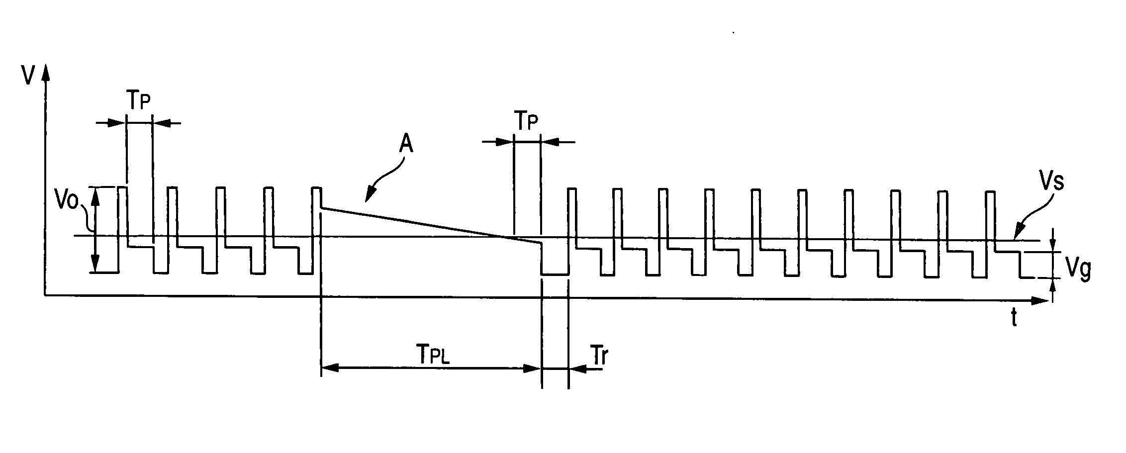
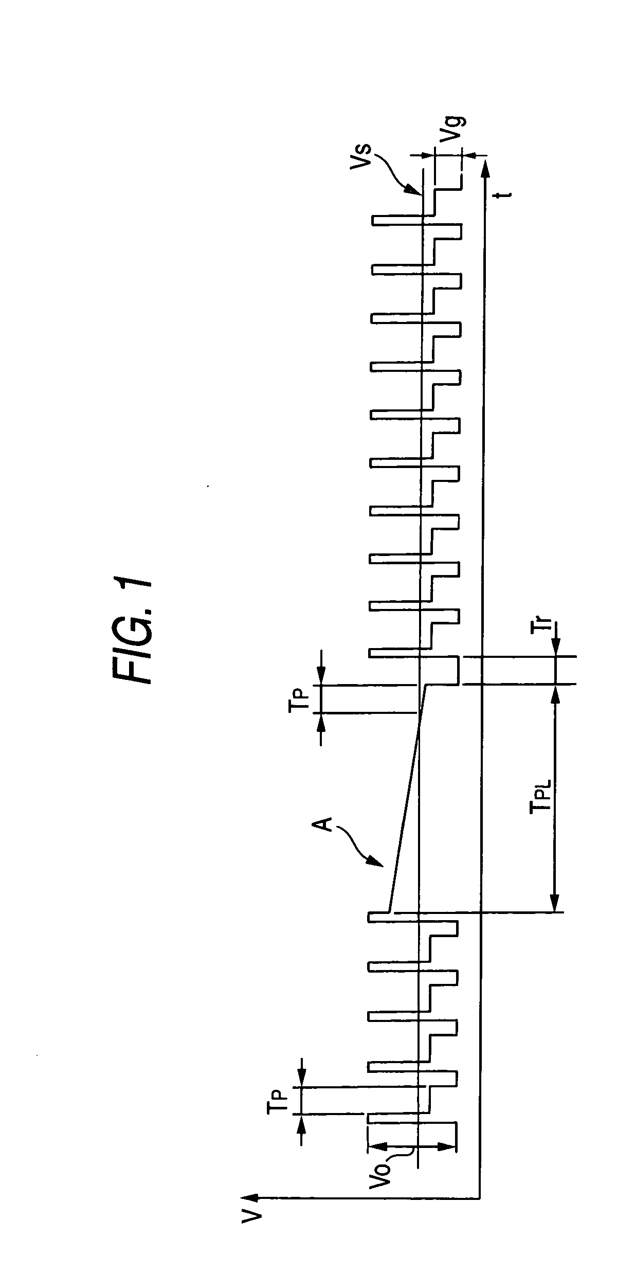
[0029]FIG. 1 is a schematic illustration showing an example of a wave-form of voltage impressed between electrodes of a conventional electric discharge machine by which a workpiece made of insulating material or high resistance material is machined. In the drawing, reference mark t is time, reference mark V is voltage impressed between electrodes, reference mark V0 is electric power source voltage, reference mark Vg is arc voltage, reference mark Vs is electric discharge detection voltage, reference mark TP is a predetermined electric discharge pulse width, reference mark TPL is an electric discharge pulse width longer than electric discharge pulse width TP which appears at a certain frequency, and reference mark Tr is recess time.

[0030] In the case where electric discharge machining is conducted by a conventional electric discharge machine, by which a workpiece made of insulating material or high resistance material is machined, while a constant electric discharge pulse width TP i...

embodiment 2

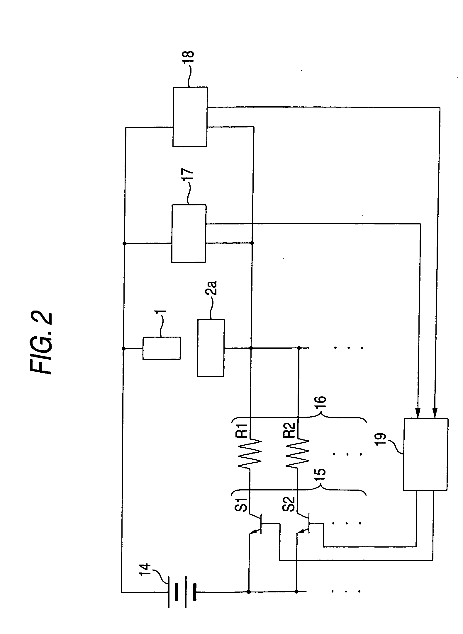
[0052]FIG. 7 is a schematic illustration showing a composition of an electric discharge machine of Embodiment 2 of the present invention. Like reference characters are used to indicate like parts in FIG. 2 showing Embodiment 1 and FIG. 7 showing Embodiment 2. In FIG. 7, reference numeral 21 is a voltmeter which is a measurement member for measuring voltage impressed between the electrodes, and the thus measured value is sent to the control member 19. In the case where voltage between the electrodes measured by the voltmeter 21 becomes a value not higher than the first reference voltage, which is voltage that has been set at a value close to the electric power source voltage not higher than the electric power source voltage, it is judged that electric discharge has started.

[0053] At a point of time when a predetermined period of time (for example, a period of time corresponding to T0 shown in FIG. 3) has passed, a signal is sent from the control member 19 to the voltmeter 21. At thi...


PUM

PropertyMeasurementUnit
arc voltage Vgaaaaaaaaaa
surface roughnessaaaaaaaaaa

Abstract

An electric discharge machine for machining a workpiece (2a) made of insulating material or other materials comprises: a first comparison member (17) for comparing voltage (V) between the electrodes of the electrode (1) and the workpiece (2a) with the first reference voltage (V1) which is set at a value close to electric power source voltage (V0) not higher than electric power source voltage (V0); a second comparison member (18) for comparing voltage (V) between the electrodes with the second reference voltage (V2) which is set at a value lower than the first reference voltage (V1); and a control member (19) for setting a short electric discharge pulse width (TP1) in the case where voltage (V) between the electrodes is lower than the second reference voltage (V2) according to the result of comparison conducted by the second comparison member (18) at a point of time when a predetermined period of time (T0) has passed from the time when voltage (V) between the electrodes becomes lower than the first reference voltage (V1) according to the result of comparison conducted by the first comparison member (17), and for setting a long electric discharge pulse width (TP2) in the case where the voltage between the electrodes is higher than the second reference voltage (V2). This electric discharge machine is capable of stabilizing the machining of the workpiece (2a) made of insulating material or other materials and also capable of enhancing quality of a machined face.

Description

TECHNICAL FIELD [0001] The present invention relates to improvements in an electric discharge machining method and electric discharge machine for machining a workpiece when machining electric power is supplied between the workpiece, which is made of insulating material or high resistance material, and an electrode so that pulse-like electric discharge is generated between the electrodes. BACKGROUND ART [0002]FIGS. 8A to 8E are schematic illustrations showing a mechanism of electric discharge machining. In the drawing, reference numeral 1 is an electrode, reference numeral 2 is a workpiece, reference numeral 3 is an arc column, reference numeral 4 is a working solution, and reference numeral 5 represents chips produced in the process of electric discharge machining. The workpiece 2 is being machined by electric discharge machining through the cycle from the following items (a) to (e) which correspond to FIG. 8A to FIG. 8E. Each item is described as follows. Item (a) is a process in w...

Claims


Application Information

Patent Timeline
Patent Type & Authority Applications(United States)
IPC IPC(8): B23H1/02B23H9/00
CPCB23H1/02B23H9/00B23H1/022
Inventor MOHRI, NAOTAKEFUKUZAWA, YASUSHIGOTO, AKIHIROMAGARA, TAKUJI
Owner MITSUBISHI ELECTRIC CORP
Why Eureka
Try Eureka