Decurl unit and printing device

a printing device and decurl technology, applied in the direction of thin material processing, transportation and packaging, filament handling, etc., can solve the problem of unfavorable interfering with the size reduction of the whole decurl unit, and achieve the effect of tight curling, decreasing the amount of roll paper, and decreasing the remaining amount of roll paper

Active Publication Date: 2005-05-12
SEIKO EPSON CORP
View PDF1 Cites 6 Cited by
  • Summary
  • Abstract
  • Description
  • Claims
  • Application Information

AI Technical Summary

Benefits of technology

[0015] In the decurl unit of the invention, said shift mechanism may move said curl elimination module to approach the roll paper shaft and thereby increase a contact area of said curl elimination module with the roll paper, as the remaining amount of the roll paper decreases.
[0016] In the decurl unit of the invention, the shift mechanism may move the curl elimination module to approach the roll paper shaft and thereby increase a contact angle ∠PQR of the curl elimination module with the roll paper. Here, the contact angle ∠PQR is defined by a position P where the roll paper drawn out of the roll paper holder comes into contact with the curl elimination module, a center position Q of the curl elimination module, and a position R where the roll paper moves away from the curl elimination module, as the remaining amount of the roll paper decreases. The inner roll of the roll paper naturally has the tighter curl. The increase in contact angle ∠PQR of the curl elimination module with the roll paper with a decrease in remaining amount of the roll paper thus effectively eliminates the tighter curl of the roll paper.

Problems solved by technology

This undesirably interferes with size reduction of the whole decurl unit.

Method used


Image

  • Decurl unit and printing device
  • Decurl unit and printing device
  • Decurl unit and printing device

Examples


Embodiment Construction

[0030] One mode of carrying out the invention is discussed below as a preferred embodiment with reference to the accompanied drawings.

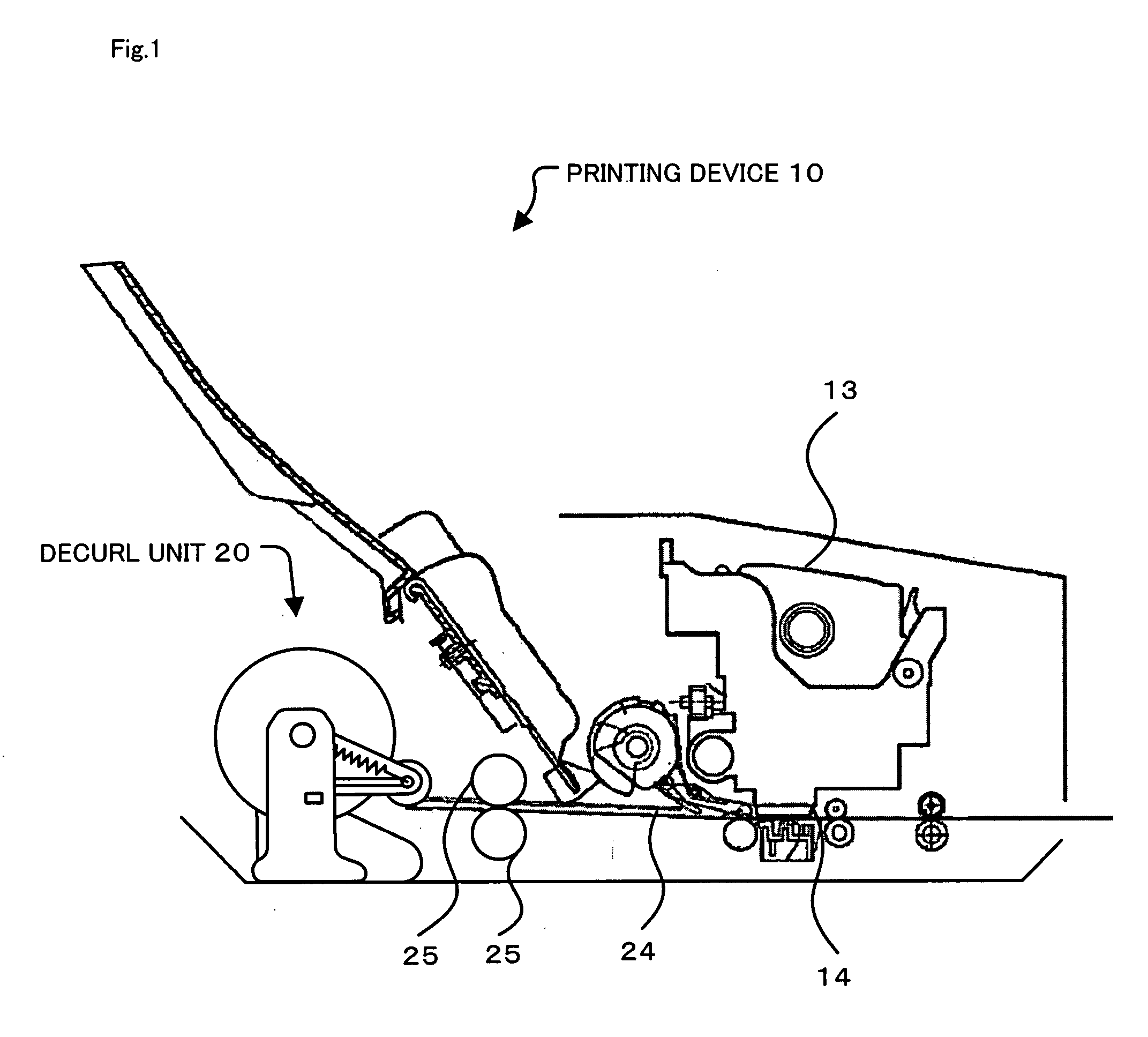
[0031]FIG. 1 schematically illustrates the structure of a printing device 10 in one embodiment of the invention. As shown in FIG. 1, the printing device 10 of the embodiment is an inkjet printer that feeds roll paper 21, which is kept on a decurl unit 20 in a rotatable manner, by means of a pair of conveyance rollers 25, while ejecting ink from a print head 14 of an ink cartridge 13 to print an image on the roll paper 21.

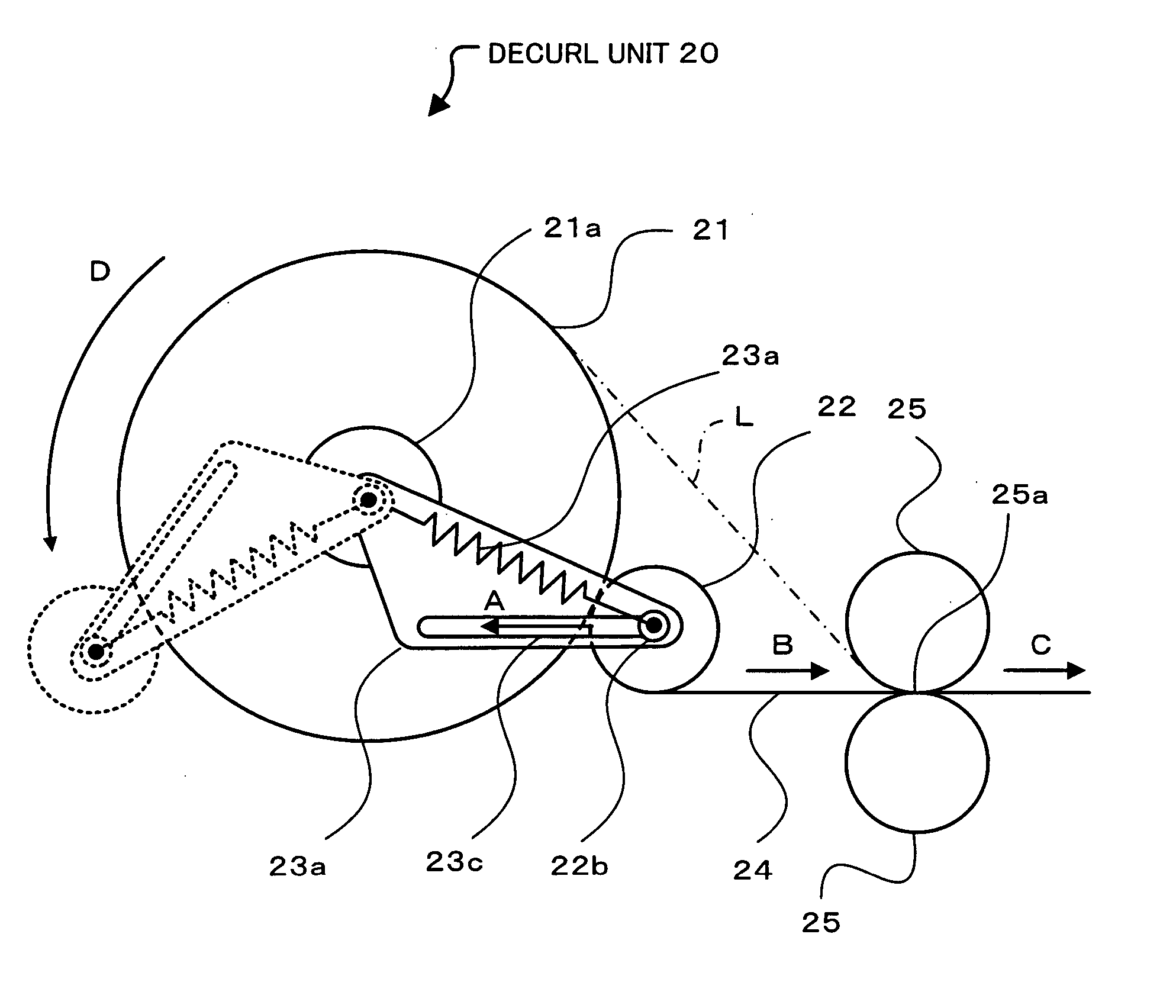
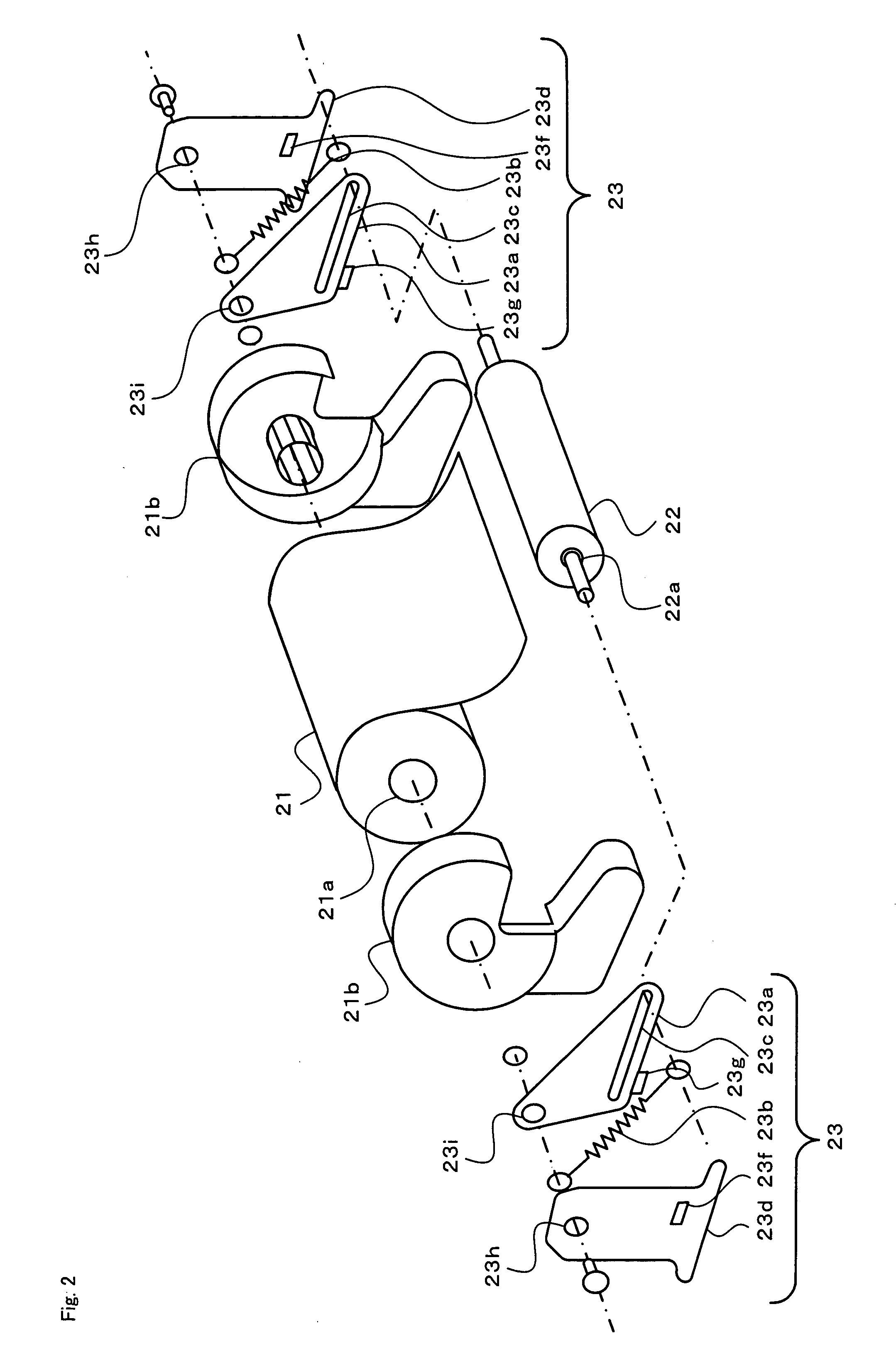
[0032]FIG. 2 is a decomposed perspective view of the decurl unit 20, and FIG. 3 is a side view of the decurl unit 20. The decurl unit 20 has the roll paper 21, a pair of roll paper holders 21b, a decurl roller 22, a shift mechanism 23, and the pair of conveyance rollers 25. The roll paper 21 is a cylindrical roll of printing paper 24 as a printing medium, which is wound clockwise on a roll paper shaft 21a. For convenience of subsequ...


PUM


Abstract

A decurl roller 22 of a decurl unit 20 is an axially rotatable member that eliminates curl of printing paper 24 drawn out of roll paper holders 21b. The decurl roller 22 is pressed by tension springs 23b, which are respectively spanned between the periphery of a roll paper shaft 21a of roll paper 21 and a roller shaft 22a of the decurl roller 22, to be continuously in contact with a cylindrical face of the roll paper 21 wound in a cylindrical roll. The decurl roller 22 moves to approach the roll paper shaft 21a with a decrease in remaining amount of the roll paper 21. As the remaining amount of the roll paper 21 decreases, the decurl roller 22 linearly moves along guide rails 23c, which are formed in support members 23a, toward an eccentric position from the roll paper shaft 21a to increase a contact area and a contact angle ∠PQR of the decurl roller 22 with the printing paper 24.

Description

BACKGROUND OF THE INVENTION [0001] 1. Field of the Invention [0002] The present invention relates to a decurl unit and a printing device. [0003] 2. Description of the Prior Art [0004] One proposed decurl unit attached to a printing device, which uses recording roll paper as a printing medium, is capable of adequately eliminating curl with a decrease in remaining amount of the roll paper. For example, in a decurl unit 50 disclosed in Japanese Patent Laid-Open Gazette No. 9-25036 (see FIG. 7), a support member 522a is attached to a pivot shaft 522b in a rotatable manner to support a decurl roller 522. A torque clutch (not shown) works to transmit a practically constant torque to the pivot shaft 522b. As the remaining amount of roll paper 521 decreases (see the one-dot chain line in FIG. 7), the torque clutch rotates the pivot shaft 522b and moves the decurl roller 522 in a direction to be pressed against the roll paper 521 (that is, in a direction of an arrow F in FIG. 7). This action...

Claims


Application Information

Patent Timeline
Patent Type & Authority Applications(United States)
IPC IPC(8): B65H23/08B65H23/16B65H23/34
CPCB65H23/34
Inventor MATSUGI, HIRONORI
Owner SEIKO EPSON CORP
Why Eureka
Try Eureka