Power controller

a technology of power controller and power supply, applied in the direction of electric variable regulation, electrical equipment, instruments, etc., can solve the problems of wasteful energy consumption, and achieve the effect of reducing the output voltag

Inactive Publication Date: 2005-05-12
ORION ELECTRIC CO LTD
View PDF2 Cites 7 Cited by
  • Summary
  • Abstract
  • Description
  • Claims
  • Application Information

AI Technical Summary

Benefits of technology

[0012] With the configuration set forth above, the output voltage serving as the reference of the output voltage stabilized circuit in a standby mode is switched to a different output voltage having a level which is higher than a level in a normal mode so that if the output voltage stabilized circuit effects feedback control relative to the power circuit based on the high-level output voltage, it is possible to realize a significant reduction of the output voltage. That is, in the case where the high-level output voltage is reduced to a critical value of the output voltage of the output voltage stabilized circuit, there occurs the reduction of the voltage in the power circuit in response to the turn ratio of the secondary winding even for the output voltage other than the high-level output voltage, so that the entire output voltage having multiple different levels can be significantly reduced. Accordingly, there occurs the reduction of the loss of the voltage by the amount corresponding to the significant reduction of the entire output voltage at the secondary windings.

Problems solved by technology

On the one hand, there is a problem that power is consumed even in a non-use state, thereby consuming wasteful energy.

Method used


Image

  • Power controller
  • Power controller
  • Power controller

Examples


Embodiment Construction

[0016] An embodiment of the invention is now described in detail. Since the embodiment is a preferable concrete example for carrying out the invention, and various technical limitations are made, but the invention is not limited to the embodiment unless it is clearly described to limit the invention.

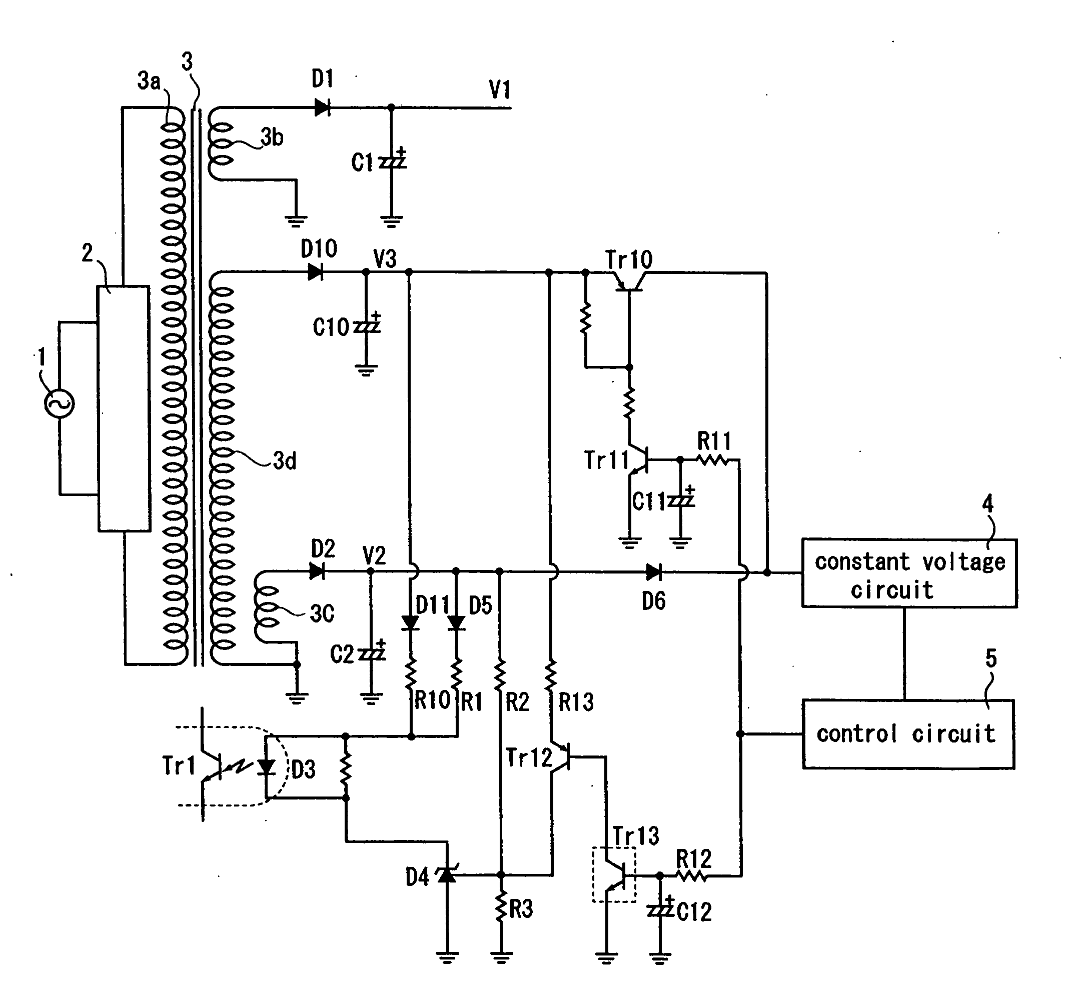
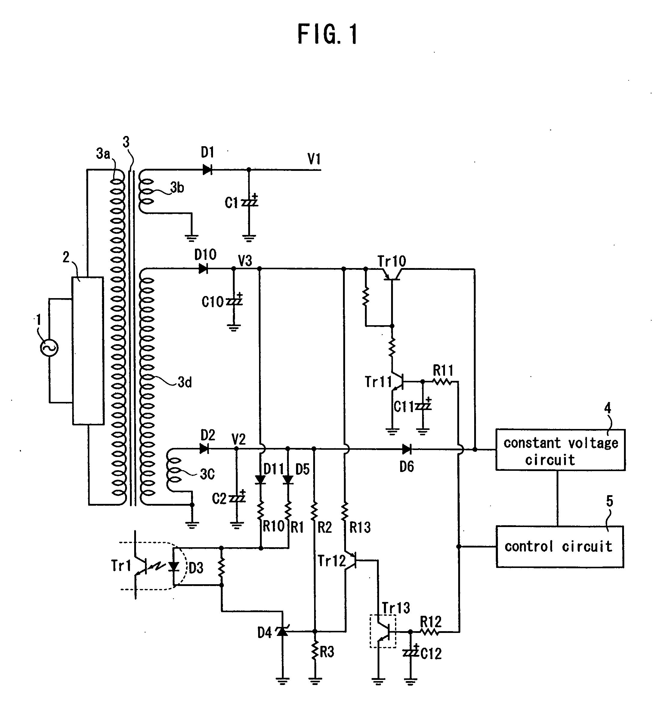
[0017]FIG. 1 is a circuit configuration according to an embodiment of the invention. In FIG. 1, constituents which are depicted by the same reference numerals as those in FIG. 2 show the same circuits and the like as explained in FIG. 2.

[0018] A winding 3d is provided in a power transformer 3 in addition to windings 3b and 3c serving as output windings of a secondary winding as explained in FIG. 2. The winding 3d is set to be larger in turn ratio than the windings 3b and 3c. A rectifying diode D10 and an electrolytic capacitor C10 for smoothing are connected to the winding 3d for supplying an output voltage V3 to the rectifying diode D10 and the electrolytic capacitor C10 for smoothing...


PUM


Abstract

It is an object of the invention to provide a power controller in the conventional circuit configuration capable of realizing significant reduction of a voltage in a standby state. The power controller comprises a power transformer which is connected to a commercial power via a switching power control circuit, and has first to third output windings at a secondary winding, wherein a reference voltage to be inputted to an error amplifier is an output voltage outputted from the first output winding in a normal mode while it is switched to an output voltage outputted from the third output winding in a standby mode. A significant reduction of a voltage can be realized in a standby mode by switching the reference voltage to the output voltage outputted from the third output winding which is higher than the output voltage outputted from the first output winding.

Description

FIELD OF THE INVENTION [0001] The invention relates to a power controller for use in electronic equipment such as a television receiver, and the like for enabling reduction of power consumption in a standby mode. BACKGROUND OF THE INVENTION [0002] There is electronic equipment such as a television receiver and so forth to which a power is supplied even in a state where electronic equipment is not used (hereinafter referred to as non-use state), thereby setting it at a standby mode. The electronic equipment can be set at a use-state in a short time when it is rendered in such a standby state, thereby enhancing the convenience thereof. On the one hand, there is a problem that power is consumed even in a non-use state, thereby consuming wasteful energy. [0003] To cope with such a problem, JP 11-215819A discloses improvement of efficiency by intermittently oscillating a switching power controller in a standby mode. This is caused by the fact that since an oscillation frequency of the sw...

Claims


Application Information

Patent Timeline
Patent Type & Authority Applications(United States)
IPC IPC(8): H02J1/00G05F1/00G05F1/577H02M7/06
CPCG05F1/577
Inventor TANI, KATSUHIKO
Owner ORION ELECTRIC CO LTD
Why Eureka
Try Eureka