Dynamic magnetic anomaly compensation

a magnetic anomaly compensation and magnetic field technology, applied in direction finders using ultrasonic/sonic/infrasonic waves, instruments, calibration apparatuses, etc., can solve problems such as the acute problem of ascertaining accurate position upon acoustic network failure, and the interference of objects in water with the acoustic signals from the network,

Inactive Publication Date: 2005-05-12
SONICWORKS
View PDF4 Cites 75 Cited by
  • Summary
  • Abstract
  • Description
  • Claims
  • Application Information

AI Technical Summary

Benefits of technology

[0030] The gradients allow the prediction of the effect of the anomaly and are applied to correct a compass directly. Since one has three pieces of information from each

Problems solved by technology

Oftentimes, however, objects in the water interfere with the acoustic signals from the network as, for instance, when divers or other objects block these signals.
The problem of ascertaining accurate position upon acoustic network failure becomes acute due to the presence of ferromagnetic objects such as ship hulls, and fluctuating magnetic fields caused by electric motors.
Fluctuating magnetic fields generated by nearby electric motors such as the ones used by the propulsion system of the remotely operated vehicle itself will also affect the guidance system of the remotely operated vehicle.
While in the past there have been a great number of static magnetic compensation systems, such as that described in U.S. Pat. No. 6,173,501, compensation of compasses in such static environments is not applicable to dynamically changing situations in which a compass is not at a fixed distance from a ferromagnetic source.
However, in the situation where either divers or remotely operated vehicles operate near a ship hull, there needs to be a dynamic magnetic anomaly compensation system that can provide heading accuracies unperturbed by the near field magnetic anomalies due to ferromagnetic objects or

Method used


Image

  • Dynamic magnetic anomaly compensation
  • Dynamic magnetic anomaly compensation
  • Dynamic magnetic anomaly compensation

Examples


Embodiment Construction

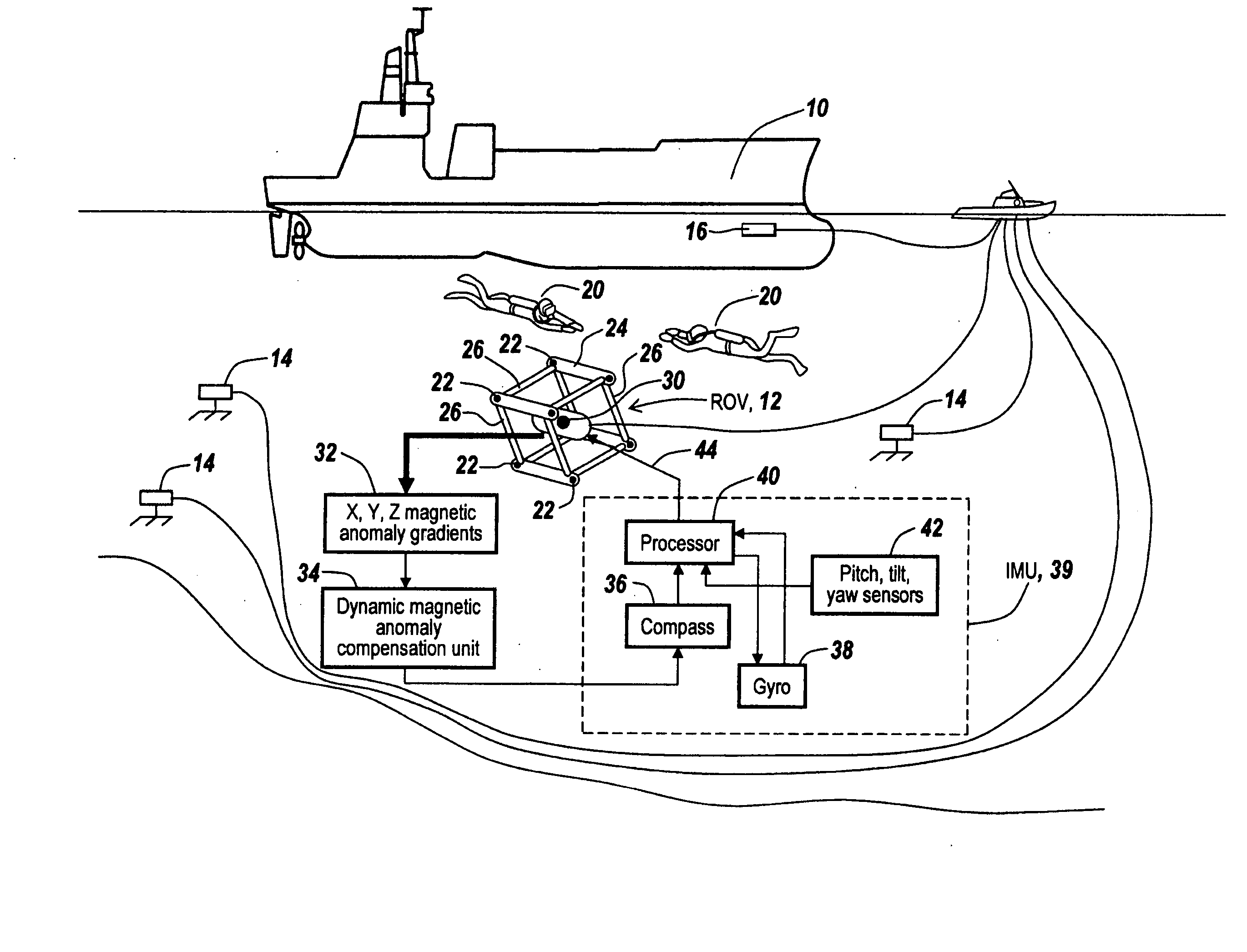
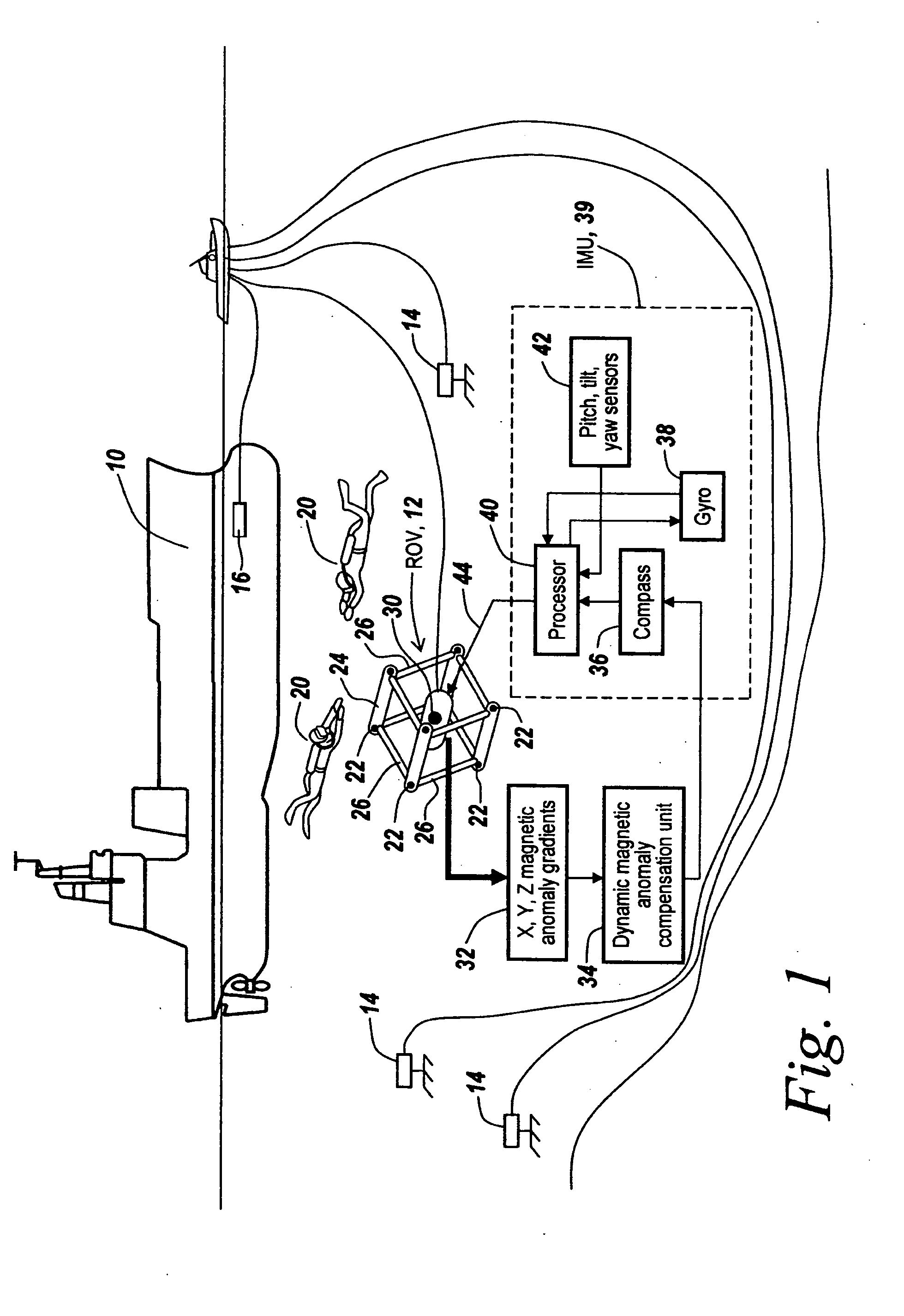
[0050] Referring now to FIG. 1, when it is desirable to do an in-water survey of a ship hull 10, in accordance with the aforementioned patent application, it is desirable to provide a survey robot or remotely operated vehicle ROV 12 to fly around the ship hull and to measure the thickness of the ship hull at a wide variety of locations using acoustic techniques.

[0051] The location of ROV 12 is initially determined through a network of transceivers 14 that are tethered to the sea floor and which, in combination with a pinger hydrophone 16 as described in the above-mentioned patent, provide for the instantaneous position of the ROV with respect to the ship's hull.

[0052] The exact position of the ROV relative to the ship's hull is important to be able to do a survey in which the survey points are no more than one centimeter apart. It is the purpose of the surveying ROV to be able to scan the entire hull and make thickness measurements relative to the hull at points whose location acc...


PUM


Abstract

An array of three-axis magnetometers used for dynamic magnetic anomaly compensation are located at the corners of a parallelopiped, with pairs of magnetometer outputs used to derive a magnetic anomaly gradient vector used to compensate a compass and/or the output of a gyroscope in an inertial management unit. The system may be used in a neutrally buoyant remotely operated vehicle to permit ascertaining of course and position in the absence of surface control signals.

Description

RELATED APPLICATIONS [0001] This application claims rights under 35 USC § 119(e) from U.S. Provisional Application Ser. No. 60 / 518,158 filed Nov. 6, 2003, the contents of which are incorporated herein by reference.FIELD OF THE INVENTION [0002] This invention relates to magnetic anomaly detection systems and more particularly to a system for using detected magnetic anomaly gradients to compensate either electronic compasses or gyroscopes for near field anomalies due to the presence of ferromagnetic objects and fluctuating magnetic fields. BACKGROUND OF THE INVENTION [0003] As described in U.S. patent application Ser. No. 10 / 935,986 filed Sep. 8, 2004 by Steven Greelish entitled “Method and Apparatus For Performing an Ultrasonic Survey,” incorporated herein by reference, a system is disclosed for use in hull surveying in which a network of acoustic elements is placed on the ocean floor and in which the exact position of a fiducial point on the hull is established. [0004] In one embodi...

Claims


Application Information

Patent Timeline
IPC IPC(8): G01R33/025
CPCG01R33/025
Inventor GREELISH, STEPHEN
Owner SONICWORKS
Why Eureka
Try Eureka