
Multiband polygonally distributed phased array antenna and associated methods

Active Publication Date: 2005-05-12
HARRIS CORP
View PDF12 Cites 9 Cited by
  • Summary
  • Abstract
  • Description
  • Claims
  • Application Information

AI Technical Summary

Benefits of technology

[0008] In view of the foregoing background, it is therefore an object of the present invention to provide a multiband antenna that has high efficiency while achieving a constant beamwidth and pattern control.
[0010] The concentric rings of dipole element arrays may be symmetrically distributed about the imaginary center point. The concentric distribution of the dipole element arrays advantageously provides a constant beamwidth when operating the multiband phased array antenna as a reflector feed. This results from the fact that a different ring can be used for each of several different frequency bands of operation. The diameter of each ring can be chosen to have about the same electrical size in its operating band, resulting in relatively constant secondary pattern beamwidth from the reflector system for all of the frequency bands. In addition, since all of the arrays have the same phase center, there is no loss of efficiency due to scan loss resulting from the phase center of the array being offset from the focal point of the reflector. This loss is always present if multiple separate apertures are utilized (e.g. spirals) since they cannot occupy the same space.
[0014] The multiband phased array antenna may further comprise a respective impedance element electrically connected between the spaced apart end portions of adjacent legs of adjacent dipole antenna elements for further increasing the capacitive coupling therebetween. Alternately, a respective printed impedance element may be adjacent the spaced apart end portions of adjacent legs of adjacent dipole antenna elements for further increasing the capacitive coupling therebetween.

Problems solved by technology

This loss is always present if multiple separate apertures are utilized (e.g. spirals) since they cannot occupy the same space.

Method used


Image

  • Multiband polygonally distributed phased array antenna and associated methods
  • Multiband polygonally distributed phased array antenna and associated methods
  • Multiband polygonally distributed phased array antenna and associated methods

Examples


Embodiment Construction

[0035] The present invention will now be described more fully hereinafter with reference to the accompanying drawings, in which preferred embodiments of the invention are shown. This invention may, however, be embodied in many different forms and should not be construed as limited to the embodiments set forth herein. Rather, these embodiments are provided so that this disclosure will be thorough and complete, and will fully convey the scope of the invention to those skilled in the art. Like numbers refer to like elements throughout, and prime, double prime and triple prime notations are used to indicate similar elements in alternative embodiments.

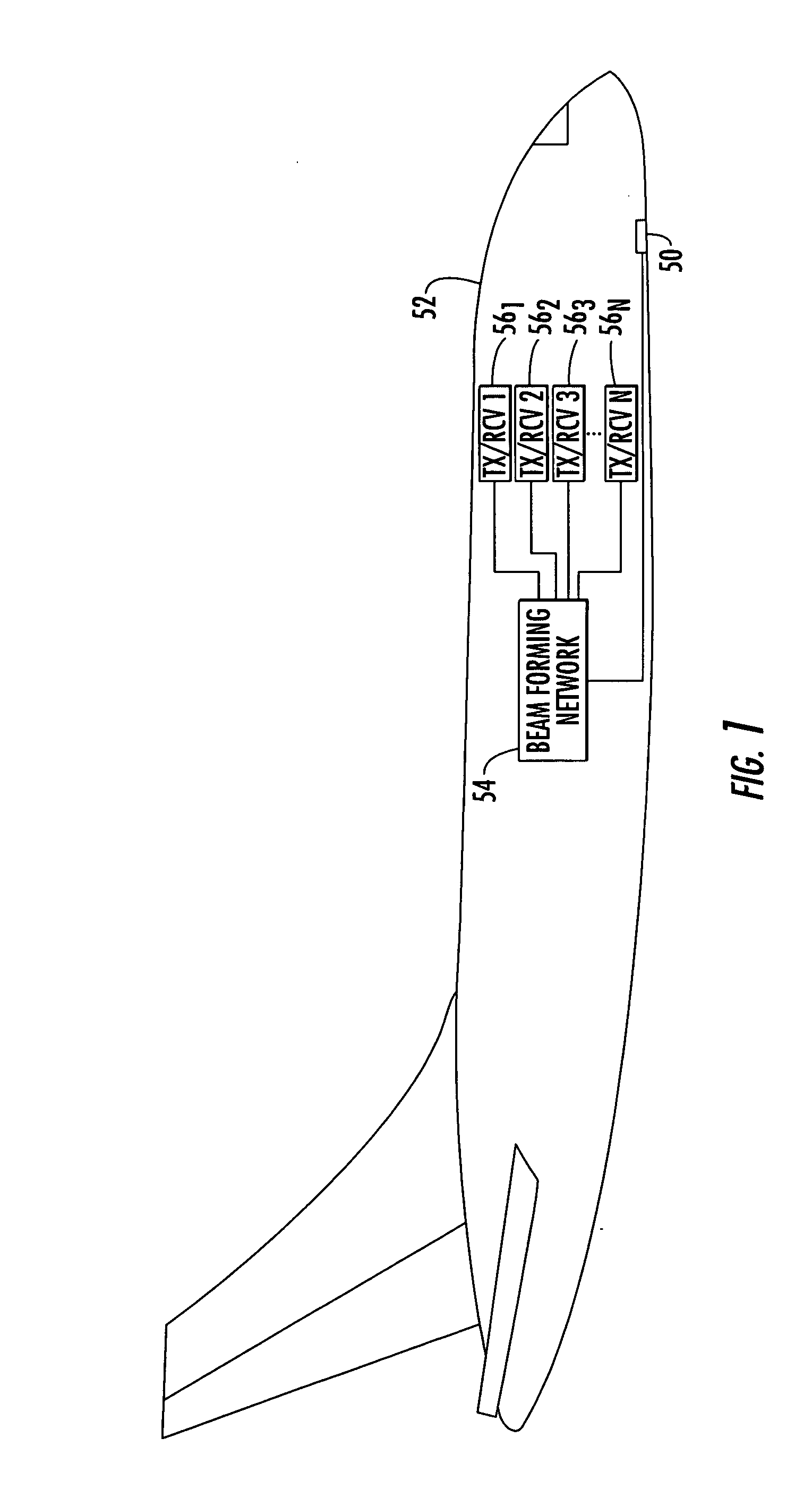
[0036] Referring initially to FIG. 1, a multiband phased array antenna 50 in accordance with the present invention will now be described. One or more multiband phased array antennas 50 may be mounted on an aircraft 52, for example. The illustrated multiband phased array antenna 50 is connected to a beam forming network (BFN) 54 which is co...


PUM


Abstract

A phased array antenna includes a substrate, and dipole element arrays extending in concentric rings about an imaginary center point on the substrate. Each dipole element array includes dipole antenna elements arranged in an end-to-end relation and having a dipole size different than a dipole size of dipole antenna elements of at least one other dipole element array. A ground plane is adjacent the dipole element arrays, and a spacing between the dipole element arrays and the ground plane is different between the dipole element arrays having different size dipole antenna elements.

Description

FIELD OF THE INVENTION [0001] The present invention relates to the field of communications, and more particularly, to a multiband phased array antenna. BACKGROUND OF THE INVENTION [0002] Existing microwave antennas include a wide variety of configurations for various applications, such as satellite reception, remote broadcasting, or military communication. The desirable characteristics of low cost, light weight, low profile and mass producibility are provided in general by printed circuit antennas. [0003] The simplest forms of printed circuit antennas are microstrip antennas wherein flat conductive elements, such as monopole or dipole antenna elements, are spaced from a single essentially continuous ground plane by a dielectric sheet of uniform thickness. An example of a microstrip antenna is disclosed in U.S. Pat. No. 6,417,813 to Durham, which is assigned to the current assignee of the present invention and is incorporated herein by reference in its entirety. [0004] The antennas a...

Claims


Application Information

Patent Timeline
IPC IPC(8): H01Q1/38H01Q3/24H01Q3/26H01Q3/30H01Q5/00H01Q5/40H01Q9/28H01Q19/10H01Q21/06
CPCH01Q1/38H01Q3/247H01Q3/26H01Q3/30H01Q5/40H01Q9/285H01Q19/10H01Q21/065H01Q9/14H01Q21/062
Inventor DURHAM, TIMOTHY E.GOTHARD, GRIFFIN K.JONES, ANTHONY M.
Owner HARRIS CORP
Learn More