
Hand-heldt type projector

a projector and hand-held technology, applied in the field of hand-held type projectors, can solve problems such as shakes of projected images, and achieve the effect of suppressing shakes of the optical axis

Inactive Publication Date: 2005-05-12
SANYO ELECTRIC CO LTD
View PDF4 Cites 57 Cited by
  • Summary
  • Abstract
  • Description
  • Claims
  • Application Information

AI Technical Summary

Benefits of technology

[0004] The present invention, in view of the aforementioned circumstances, aims at providing hand-held type projectors capable of preventing shakes of projected images due to hand shakes.
[0010] In these configurations, only the light valve or a portion or all of the optical system including the light valve is provided rotatably about the aforementioned optical axis. In this configuration, there may be provided a weight which makes it easy to maintain the light valve or a portion or all of the optical system in a horizontal attitude.
[0011] Also, a hand-held type projector according to the present invention comprises a light valve for modulating light emitted from a light source, a projection lens for projecting image light obtained by the aforementioned modulation, and vibration isolation means for suppressing shakes of the optical axis of projected images (hereinafter, this will be referred to as a second configuration in this section). This configuration prevents projection shakes, so to say, in a passive manner.
[0012] In the second configuration, the above vibration isolation means may be formed from a vibration isolation supporting member provided between a cabinet and an optical system including at least the light valve and the projection lens. Also, in this configuration, the vibration isolation supporting member may be formed from an elastic member. In the second configuration and the configurations depending thereon, only the light valve or a portion or all of the optical system including the light valve may be provided rotatably about the aforementioned optical axis of image light. In this configuration, there may be provided a weight which makes it easy to maintain the light valve or a portion or all of the optical system in a horizontal attitude.

Problems solved by technology

However, it is expected that there will be inconvenience that hand shakes cause shakes of projected images.

Method used


Image

  • Hand-heldt type projector
  • Hand-heldt type projector
  • Hand-heldt type projector

Examples


Embodiment Construction

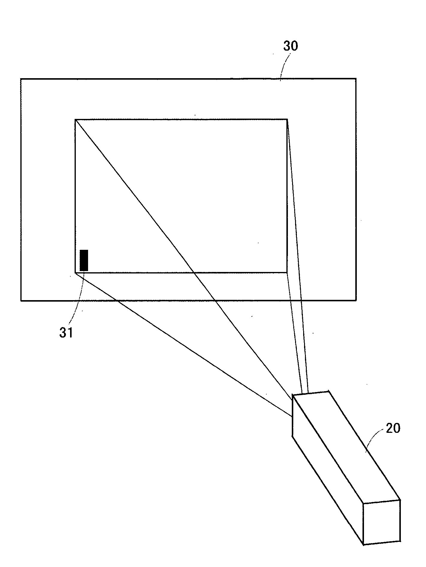
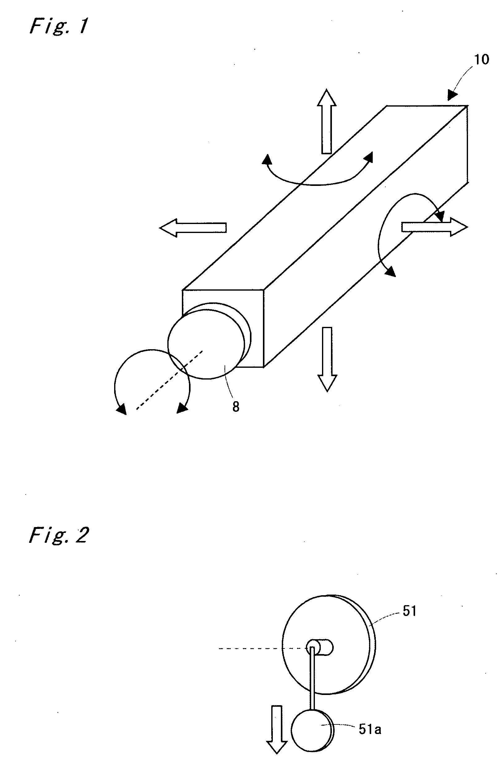
[0039] Hereinafter, hand-held type projectors according to embodiments of the present invention will be explained based on FIG. 1 to FIG. 20. FIG. 1 is an explanatory view illustrating the relation between a hand-held type projector 10 and the directions of shakes. The directions of shakes include a horizontal shake, a vertical shake, a rotational shake about a horizontal axis, a rotational shake about a vertical axis, and a rotational shake about an optical axis. These shakes can be detected by using a sensor such as an acceleration sensor (a piezoelectric vibratory gyro, a semiconductor acceleration sensor, etc.) which detects forces or variation of a member due to forces. Also, the rotational shake about the horizontal axis and the rotational shake about the optical axis can be detected by a potentiometer using a resistor. FIG. 2 is a perspective view illustrating a potentiometer 51. The potentiometer 51 is provided with a weight 51a. The detection of shakes is not limited to the...


PUM


Abstract

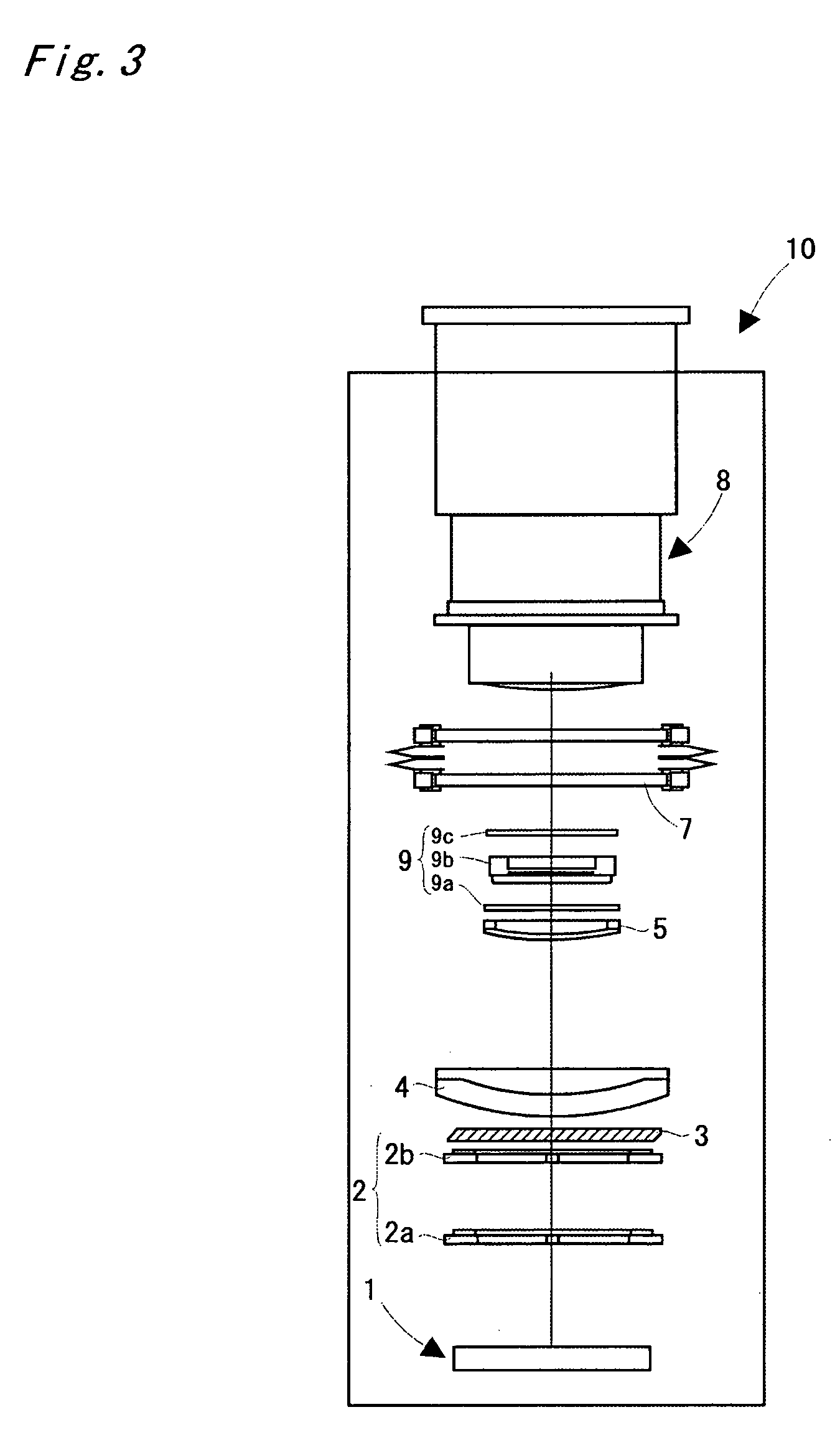
Modulated light (image light) which has been modulated by passing through a liquid crystal display panel passes through an apical angle variable prism (so-called, a vari-angle prism) and then is enlarged and projected by a projection lens. The apical angle variable prism is configured to change the prism apical angle with, for example, an electromagnetic actuator. The microcomputer calculates a projection optical axis correction value based on hand shake detection signals from a sensor and controls the aforementioned actuator based on the correction value. With this control, shakes of projected images due to hand shakes are prevented.

Description

BACKGROUND OF THE INVENTION FIELD OF THE INVENTION [0001] The present invention relates to a hand-held type projector which is small and hand-holdable. [0002] Conventionally, there have been suggested liquid crystal projectors which utilize a liquid crystal panel for image projection or projectors which utilize a light valve formed by arranging a plurality of micro mirrors. These projectors are used by placing on a desk or suspending from a ceiling. Further, a camera equipped with a hand-shake correction mechanism has been known (see JP-A No. 2000-147586). Also, a projection-type video display-device equipped with an apical angle variable prism for image shift or image tilt has been known (see JP-A No. 6-331931). SUMMARY OF THE INVENTION [0003] By miniaturizing a projector, a hand-holdable projector (hand-held type projector) may be realized. In this case, for example, during a presentation, a person who gives an explanation projects images at every key point with a hand-held type p...

Claims


Application Information

Patent Timeline
Patent Type & Authority Applications(United States)
IPC IPC(8): G03B5/00G02B27/20G03B21/00G03B29/00H04N5/225H04N5/232H04N5/74H04N17/00
CPCH04N5/7416H04N9/3194H04N9/317
Inventor YOKOTE, YOSHIHIROYOSHII, SHOUICHIKANAYAMA, HIDEYUKIIKEDA, TAKASHI
Owner SANYO ELECTRIC CO LTD
Learn More