Image forming apparatus and process cartridge

Active Publication Date: 2005-05-12
BROTHER KOGYO KK
View PDF12 Cites 15 Cited by
  • Summary
  • Abstract
  • Description
  • Claims
  • Application Information

AI Technical Summary

Benefits of technology

[0018] Therefore, another one of objects of the invention is to provide an image forming apparatus

Problems solved by technology

In this case, in this range, a transfer bias is not applied to the sheet and a transfer current leaks.
Furthermore, in an environment with a high temperature and a low humidity, the resistance of the sheet increases and the resistance of the transfer roller lowers, so that the transfer current more easily leaks.
On the other hand, the transfer current that the photoconductor drum c

Method used


Image

  • Image forming apparatus and process cartridge
  • Image forming apparatus and process cartridge
  • Image forming apparatus and process cartridge

Examples


first embodiment

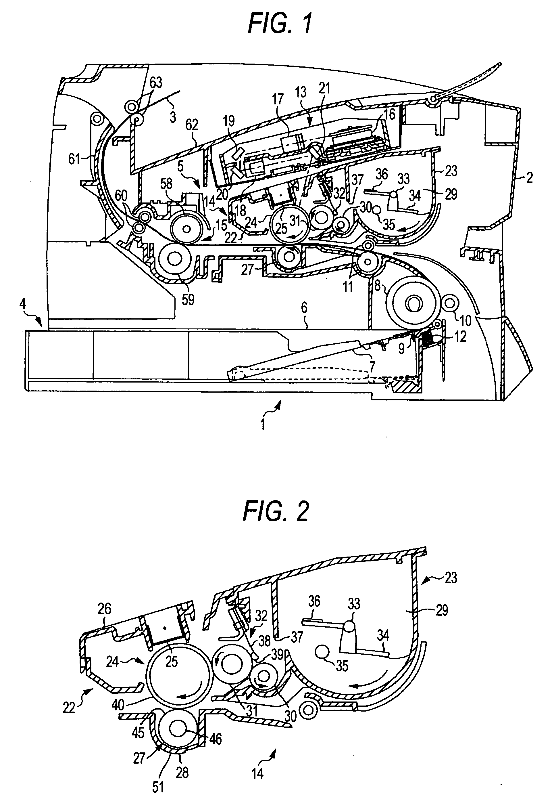
[0047]FIG. 1 is a main part side sectional view showing a laser printer as an image forming apparatus of the invention. In FIG. 1, the laser printer 1 includes a feeder part 4 for feeding a sheet 3 as a transfer medium and an image forming part 5 for forming an image on the fed sheet 3 inside a main body casing 2.

[0048] The feeder part 4 includes a paper feed tray 6 to be detachably attached to the bottom inside the main body casing 2, a sheet pressing plate 7 provided inside the paper feed tray 6, a sheet feed roller 8 and a paper feed pad 9 provided above one end of the paper feed tray 6, a paper powder removal roller is 10 disposed opposite the sheet feed roller 8, and a resist roller 11 provided at the opposite side of the paper powder removal roller 10 with respect to the sheet feed roller 8.

[0049] The sheet pressing plate 7 is provided so that a sheet 3 can be stacked thereon, and supported in a manner enabling it to swing on the end more distant from the sheet feed roller 8,...

second embodiment

[0151] Hereinafter, the invention is described with reference to the drawings. FIG. 14 is an explanatory view showing the schematic sectional configuration of a laser printer 101 as an electrophotographic image forming apparatus to which the invention is applied. FIG. 15 is a block diagram showing the electrical configuration of the laser printer 101.

[0152] The laser printer 101 shown in FIG. 14 has a feeder unit 110 for feeding a paper as a sheet at the bottom of the main body case 102. The feeder unit 110 includes a sheet pressing plate 111, a compression spring 112, and a sheet feed roller 113, and sheets P placed on the sheet pressing plate 111 are pressed against the sheet feed roller 113 by the pressing force of the compression spring 112, the top paper is separated by the rotation of the sheet feed roller 113 and supplied to the side of the resist rollers 114 and 115.

[0153] At the further downstream side in the sheet conveyance direction shown by the arrow A than the sheet f...


PUM


Abstract

An image forming apparatus includes: a transfer member that transfers a developer image onto a transfer medium to form an image on the transfer medium; a bias applying unit that applies a transfer bias to the transfer member; and a bias control unit that controls the transfer bias to be applied to the transfer member by the bias applying unit, wherein a longitudinal length of the transfer member is formed to be shorter than a width of the transfer medium having a maximum width on which the image is to be formed with the image forming apparatus.

Description

BACKGROUND OF THE INVENTION [0001] 1. Field of the Invention [0002] The present invention relates to an image forming apparatus such as a laser printer, and a process cartridge to be detachably attached to the image forming apparatus. The present invention also relates to an image forming apparatus that is configured so that a developer remaining on an image carrier after transferring is collected by a developing unit. [0003] 2. Description of the Related Art [0004] In an image forming apparatus such as a laser printer, a process cartridge including a developing roller which carries toner, a photoconductor drum which is disposed opposite the developing roller and on which an electrostatic latent image is formed, and a transfer roller which is disposed opposite the photoconductor drum to transfer a toner image onto a sheet is detachably attached. [0005] On the photoconductor drum, a toner is supplied from the developing roller, and an electrostatic latent image is developed, whereby ...

Claims


Application Information

Patent Timeline
IPC IPC(8): G03G15/16G03G21/18
CPCG03G15/1675G03G2221/183G03G2221/1606G03G21/1814
Inventor NISHIMURA, SOICHIRODEGUCHI, HIDEAKIISHIKAWA, SATORU
Owner BROTHER KOGYO KK
Why Eureka
Try Eureka