Vacuum electric arc deposition equipment

A technology of vacuum arc and deposition equipment, which is applied in the direction of vacuum evaporation plating, circuit, discharge tube, etc., and can solve the problem of low degree of freedom of layered film

Inactive Publication Date: 2004-05-12
NISSIN ELECTRIC CO LTD
View PDF0 Cites 6 Cited by
  • Summary
  • Abstract
  • Description
  • Claims
  • Application Information

AI Technical Summary

Problems solved by technology

Thus, the degree of freedom to form layered films is very low

Method used


Image

  • Vacuum electric arc deposition equipment
  • Vacuum electric arc deposition equipment
  • Vacuum electric arc deposition equipment

Examples


Embodiment Construction

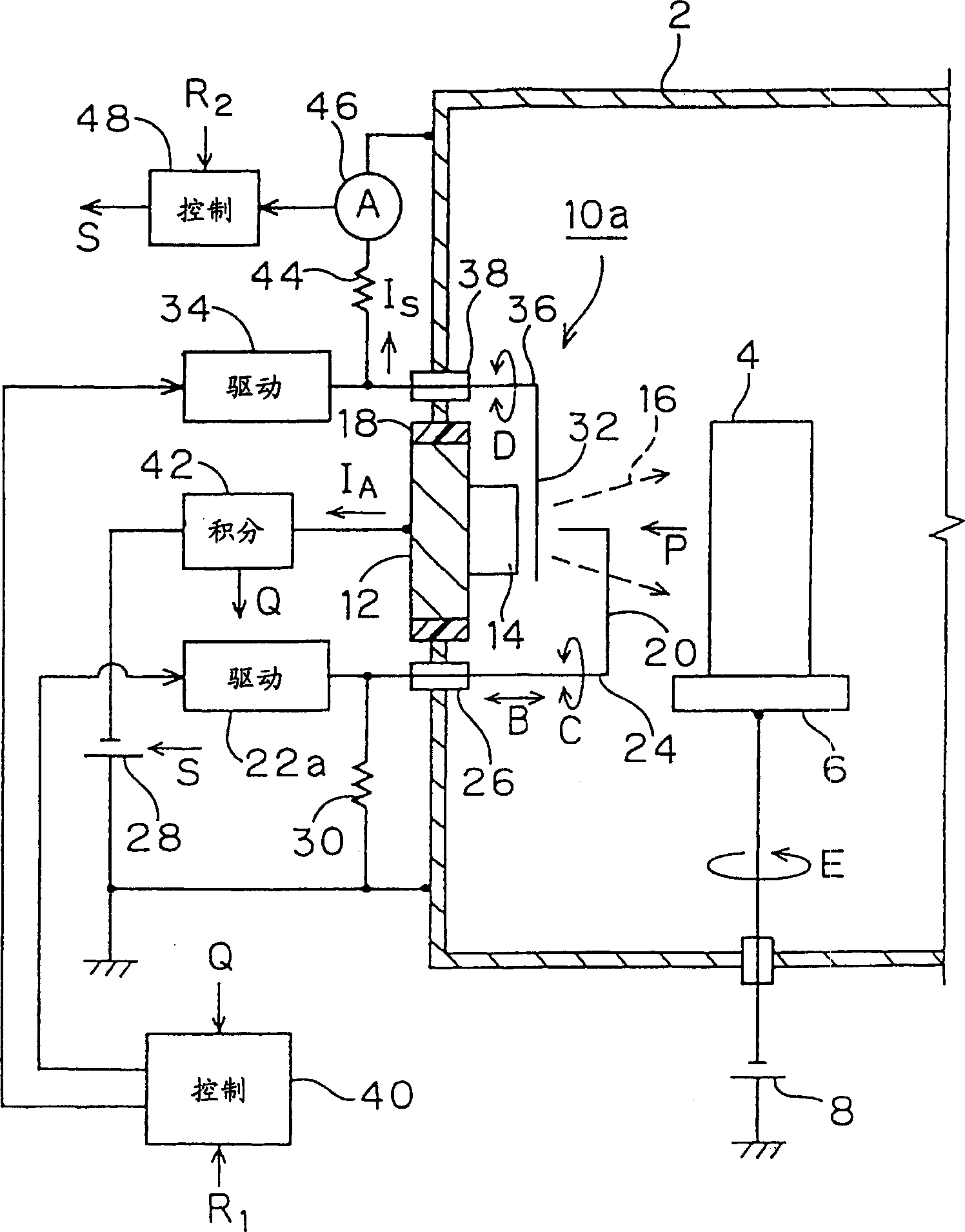
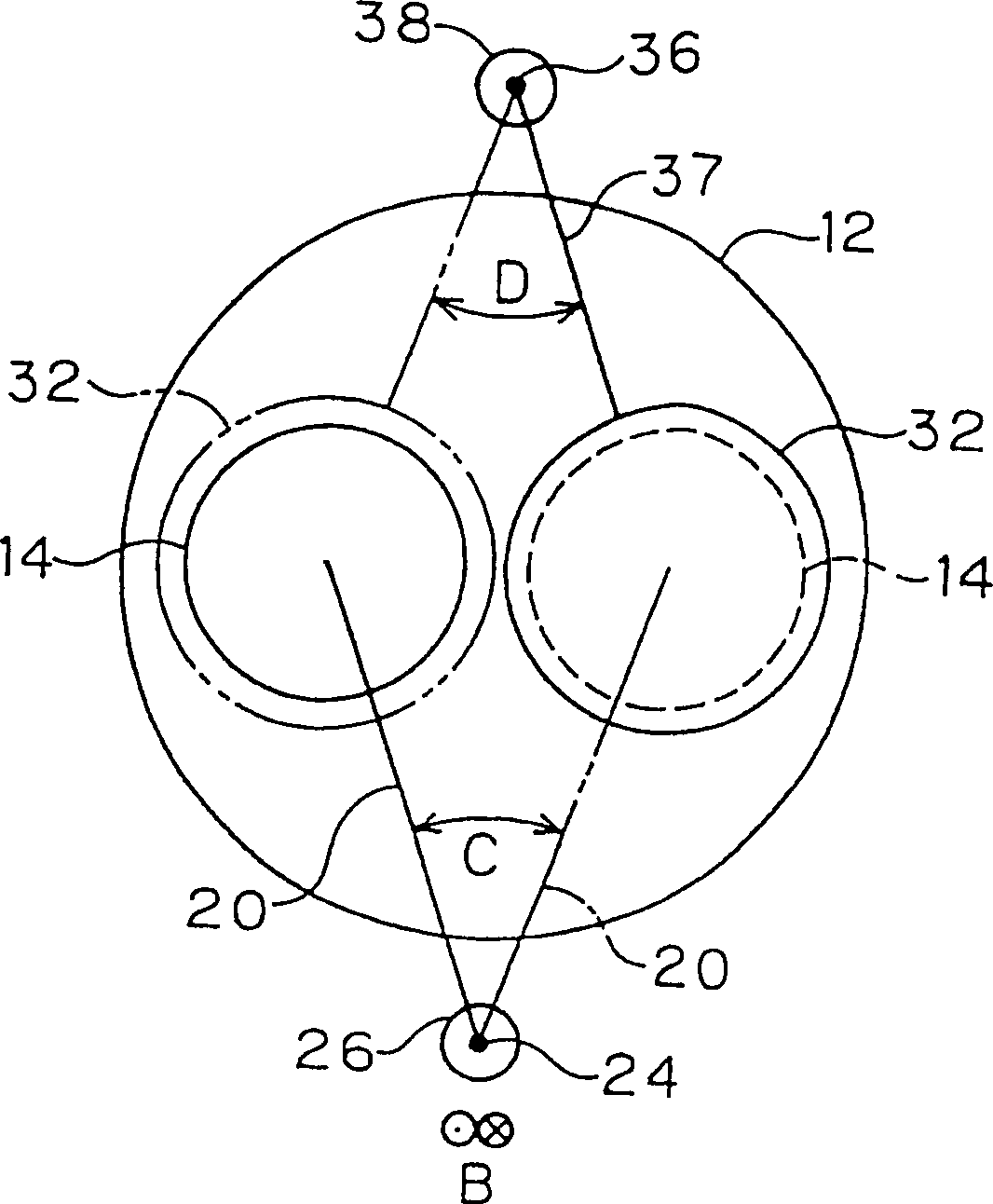
[0034] figure 1 is a sectional view showing an embodiment of a vacuum arc deposition apparatus according to the present invention. figure 2 From figure 1 The front view obtained by looking in the direction of the arrow P in , shows an example of the peripheral portion of the cathode in an arc evaporation source used in the vacuum arc deposition apparatus according to the present invention. Correspondingly, in this embodiment with Figure 4 , 5 The same or corresponding parts in the shown prior art examples will be designated with the same numerals, and the following will mainly focus on their differences from the prior art examples.

[0035] The vacuum arc deposition apparatus of the present invention has an arc evaporation source 10a instead of the arc evaporation source 10 in the prior art. As discussed above, the number of arc evaporation sources 10a may be one or more.

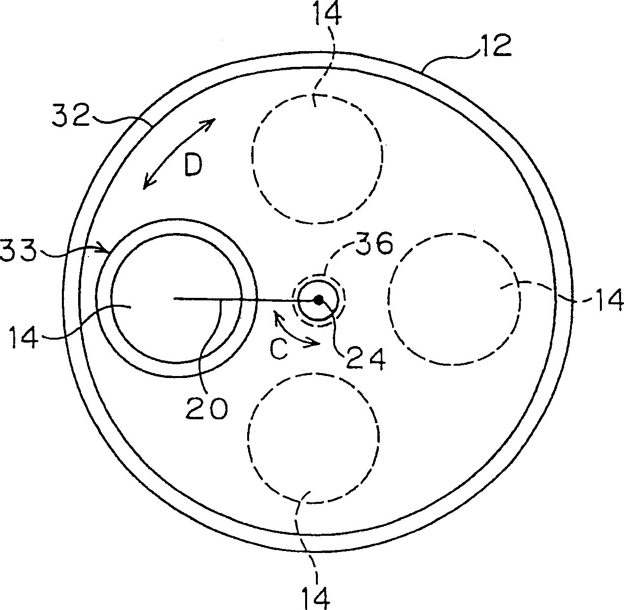
[0036] In this embodiment, the arc evaporation source 10a has: a cathode holder 12 as described ...


PUM


Abstract

An arc evaporation source constituting this vacuum arc deposition apparatus has a plurality of cathodes, a trigger electrode, a trigger drive unit, a shutter, and a shutter drive unit. The trigger drive unit changes over the position of the trigger electrode to thereby position the trigger electrode in front of a desired cathode, and connects / disconnects the trigger electrode to / from the desired cathode in the changed-over position. The shutter covers the fronts of all the cathodes except the desired cathode..: The shutter drive unit moves the shutter to thereby change over the cathode not covered with the shutter. Further, the vacuum arc deposition apparatus has a changeover control unit for controlling the shutter drive unit and the trigger drive unit to thereby change over the cathode not covered with the shutter and to thereby position the trigger electrode in front of the cathode not covered with the shutter.

Description

technical field [0001] The invention relates to a vacuum arc deposition equipment, which has an arc evaporation source, which is used for evaporating cathode material by vacuum arc discharge, and depositing the cathode material on a substrate to form a thin film. Specifically, the present invention relates to an apparatus that can prolong the time for performing thin film deposition, or increase the degree of freedom in forming a layered film. Background technique [0002] Figure 4 An example of such vacuum arc deposition equipment in the prior art is shown, Figure 5 From Figure 4 The view obtained by observing in the direction of the arrow P. [0003] The vacuum arc deposition apparatus has a vacuum chamber 2 which is evacuated by a vacuum pumping system not shown in the figure. A holder 6 is provided in the vacuum chamber 2 for holding a substrate 4 to be coated. An arc evaporation source 10 is attached to one side wall portion of the vacuum chamber 2 , and in this e...

Claims


Application Information

Patent Timeline
Patent Type & Authority Applications(China)
IPC IPC(8): C23C14/24C23C14/32H01J37/32
CPCH01J37/32009C23C14/325H01J37/32055
Inventor 入泽一彦簗岛英夫瀬户山诚
Owner NISSIN ELECTRIC CO LTD
Why Eureka
Try Eureka