

Spade drill insert having helical margins
a technology of helical margins and inserts, which is applied in the direction of swing drills, manufacturing tools, wood boring tools, etc., can solve the problems of increased heat buildup on the insert, excessive exit chatter, and reducing the stability of the spade drill, so as to achieve the effect of increasing stability
- Summary
- Abstract
- Description
- Claims
- Application Information
AI Technical Summary
Benefits of technology
Problems solved by technology
Method used
Image

Examples
Embodiment Construction
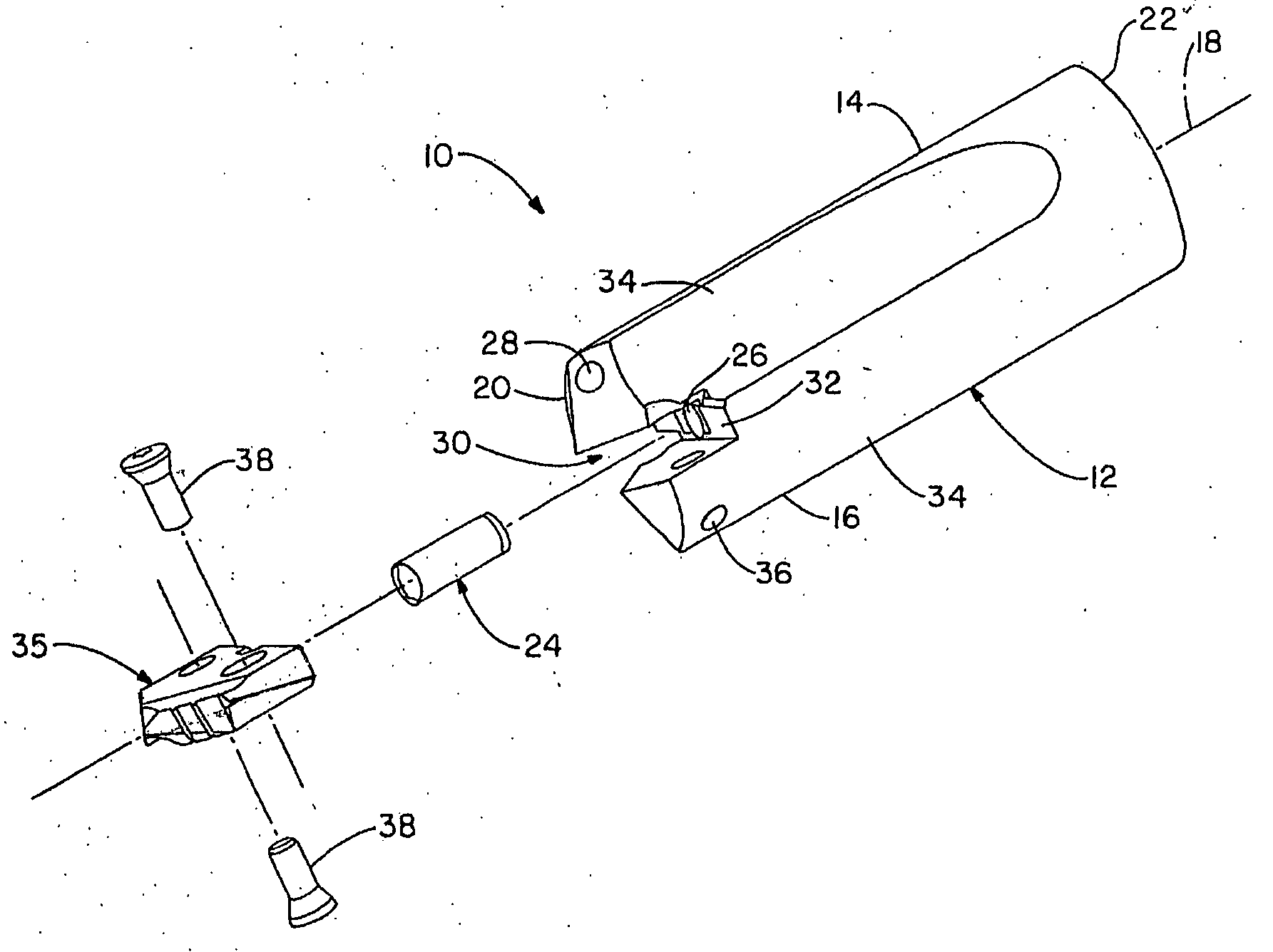
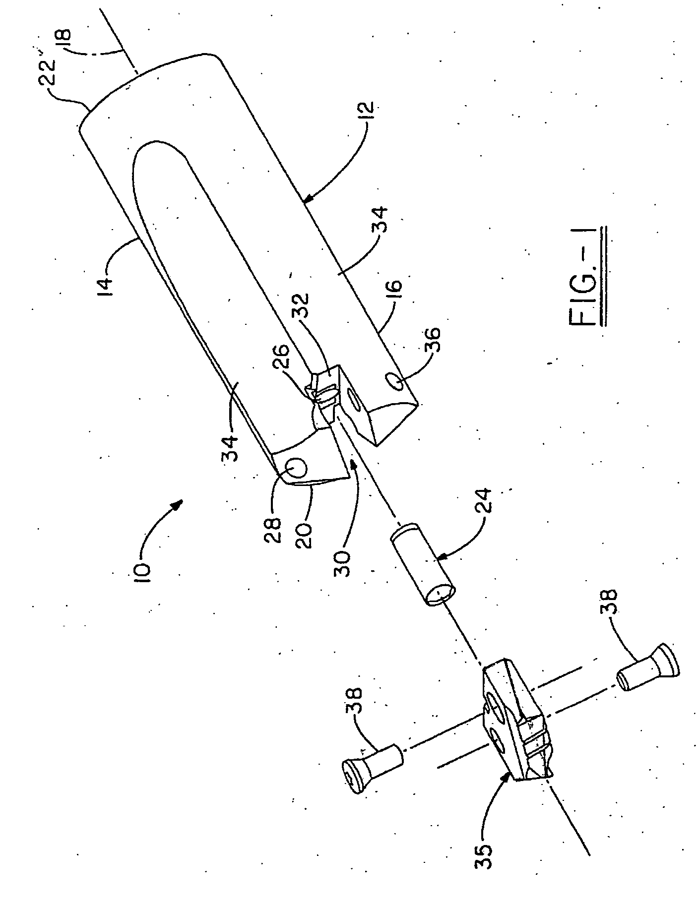
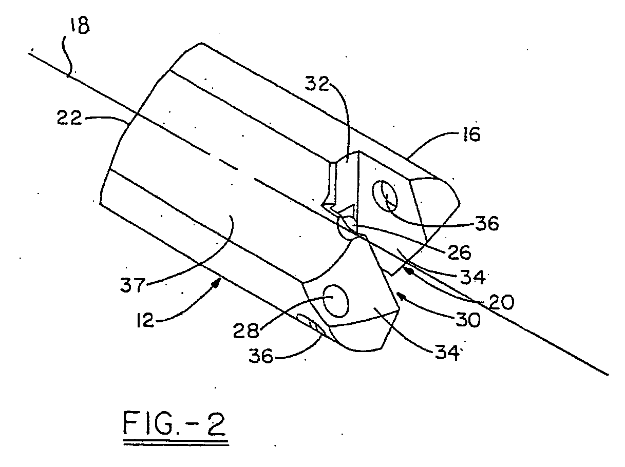
[0016] Turning now to a first embodiment of the invention, FIG. 1 illustrates a drill tool assembly 10 generally indicated. Drill tool assembly 10 comprises a holder 12, which has a body 14 and head portion 16 associated therewith. In the first embodiment, holder 12 has, in general, a cylindrical shape with a first end 20 and second end 22. As shown in FIG. 2, the first end 20 of holder 12 has a clamping or holder slot 30, which may extend across the entire diameter of the head portion 16 or, at least, over a center portion thereof at the general location of the rotational axis 18 of holder 12. The holder slot 30 has a bottom wall 32 positioned in substantially perpendicular orientation relative to the rotational axis 18 of the holder 12. In the embodiment shown, the assembly 10 may further include a locating boss or dowel pin 24, which is positioned precisely with respect to the axis 18 and extends from the bottom wall 32 of the holder slot 30. The pin 24 may be positioned within a...
PUM
| Property | Measurement | Unit |
|---|---|---|
| width | aaaaa | aaaaa |
| speed | aaaaa | aaaaa |
| stability | aaaaa | aaaaa |
Abstract
Description
Claims
Application Information