Hybrid transmission
- Summary
- Abstract
- Description
- Claims
- Application Information
AI Technical Summary
Benefits of technology
Problems solved by technology
Method used
Image
Examples
Example
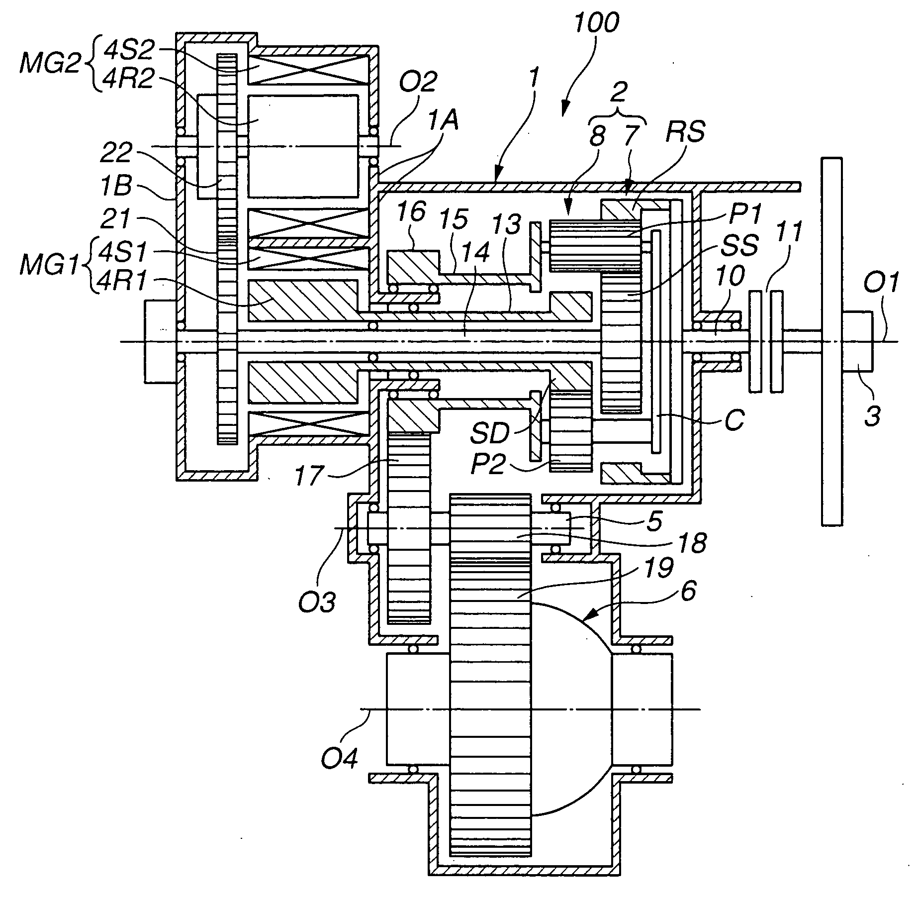
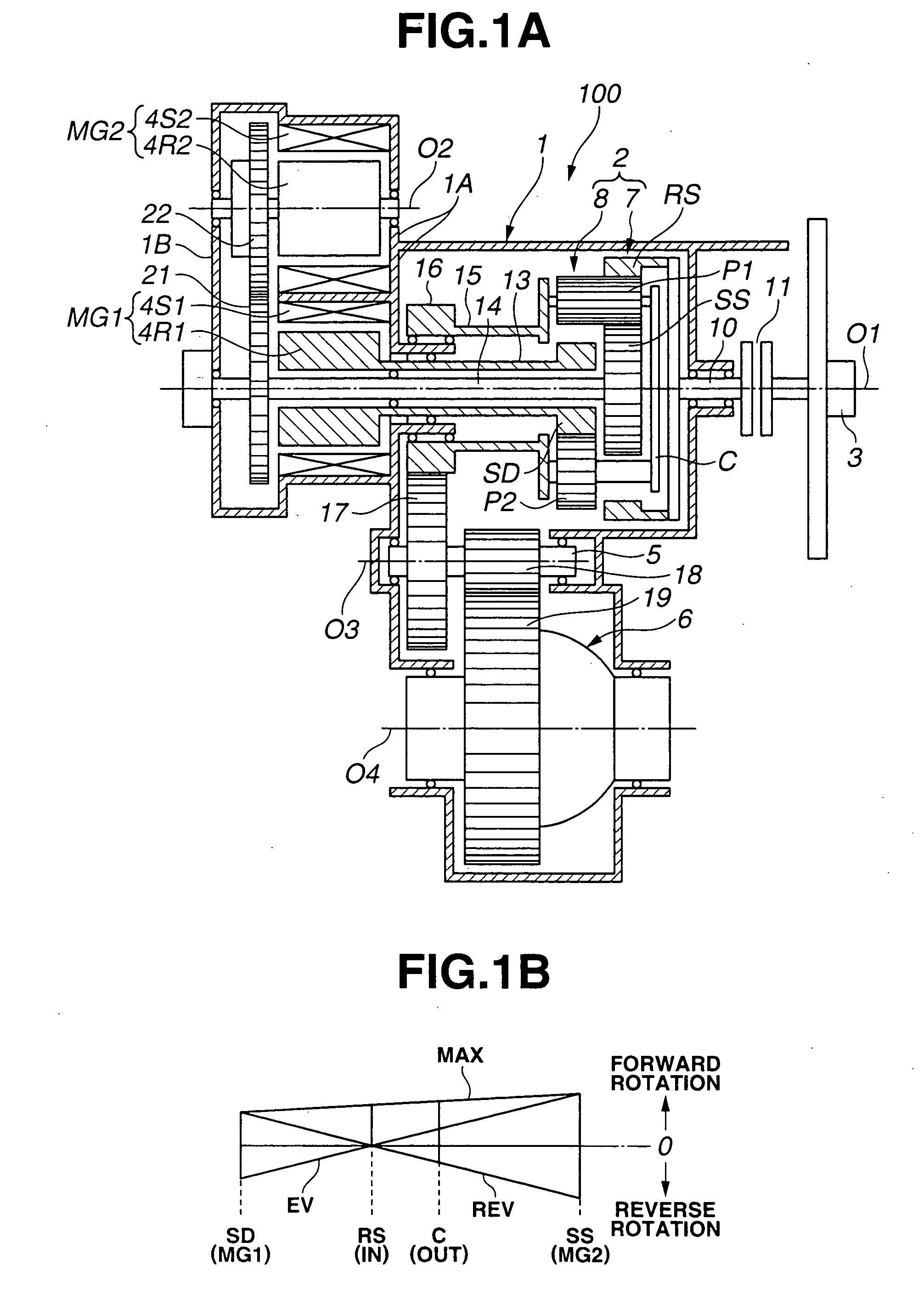
[0027] Referring to FIG. 1A, a hybrid transmission according to a first embodiment of the present invention now is explained. In this embodiment, the hybrid transmission is applied to a transaxle for a front-engine front-drive (FF) vehicle.
[0028] Hybrid transmission 100 includes transmission case 1 through which axis O1 extends, two degree-of-freedom gear mechanism 2, first motor / generator MG1 and second motor / generator MG2 which are installed in transmission case 1 along axis O1. As illustrated in FIG. 1A, two degree-of-freedom gear mechanism 2 is disposed on the right side as viewed in the figure in a direction of axis O1, and first and second motor / generators MG1 and MG2 are disposed on the left side as viewed in the figure in the direction of axis O1. Engine 3 acting as a prime power source is disposed on the outside of transmission case 1 and located on the right side of two degree-of-freedom gear mechanism 2 as shown in FIG. 1A. In FIG. 1A, there is shown only a crankshaft of...
Example
[0045] Referring to FIG. 2, there is shown the hybrid transmission of a second embodiment of the present invention. The second embodiment differs in construction of first and second motor / generators MG1 and MG2 from the first embodiment. Like reference numerals and letters denote like parts, and therefore, detailed explanations therefor are omitted. As illustrated in FIG. 2, hybrid transmission 200 includes first motor / generator MG1 as explained in the first embodiment, and second motor / generator MG2 having an axial length longer than that of first motor / generator MG1 and a diameter smaller than that of first motor / generator MG1. The axial length of second motor / generator MG2 is not longer than the axial length of hybrid transmission 200. Second motor / generator MG2 includes second rotor 4R2 rotatably supported on transmission case 1 and annular second stator 4RS fixed to transmission case 1. Second stator 4RS is enclosed in motor / generator casing 4C of transmission case 1 which is i...
Example
[0047] Referring to FIG. 3, there is shown the hybrid transmission of a third embodiment of the present invention. The third embodiment differs in that a wrapping connector driving member is used as a transmitting device for drivingly connecting central shaft 14 extending from sun gear SS with second rotor 4R2 of second motor / generator MG2, from the second embodiment using the gear train including gears 21 and 22. As illustrated in FIG. 3, hybrid transmission 300 includes wrapping connector driving member 23 such as belt or chain 23C wrapped around two wheels 23A and 23B. Wheel 23A is provided on the end portion of central shaft 14 which projects from the axial end of first rotor 4R1 into rear cover 1B. Wheel 23B is provided on the end portion of the central shaft of second rotor 4R2 which projects from the axial end of second rotor 4R2 into rear cover 1B.
PUM
Abstract
Description
Claims
Application Information
- R&D Engineer
- R&D Manager
- IP Professional
- Industry Leading Data Capabilities
- Powerful AI technology
- Patent DNA Extraction
Browse by: Latest US Patents, China's latest patents, Technical Efficacy Thesaurus, Application Domain, Technology Topic.
© 2024 PatSnap. All rights reserved.Legal|Privacy policy|Modern Slavery Act Transparency Statement|Sitemap