

Servo-controlled impacting device for orthopedic implants
- Summary
- Abstract
- Description
- Claims
- Application Information
AI Technical Summary
Benefits of technology
Problems solved by technology
Method used
Image

Examples
Embodiment Construction
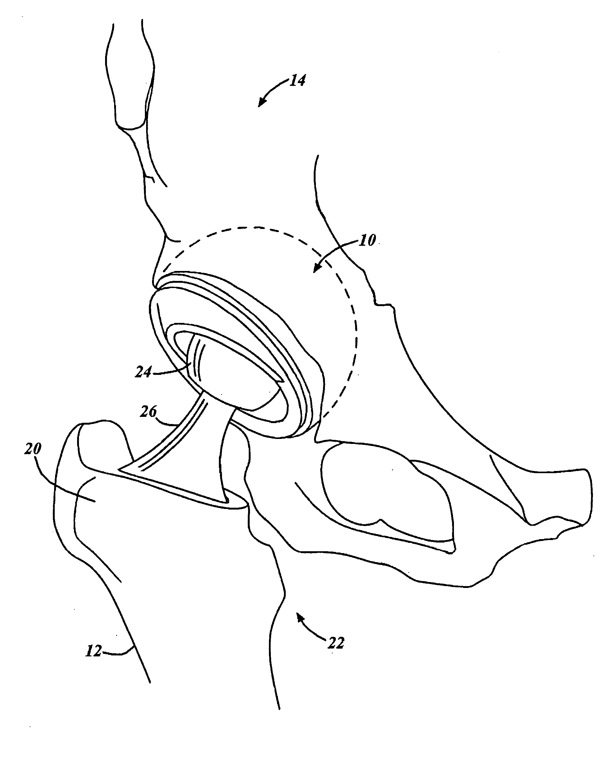
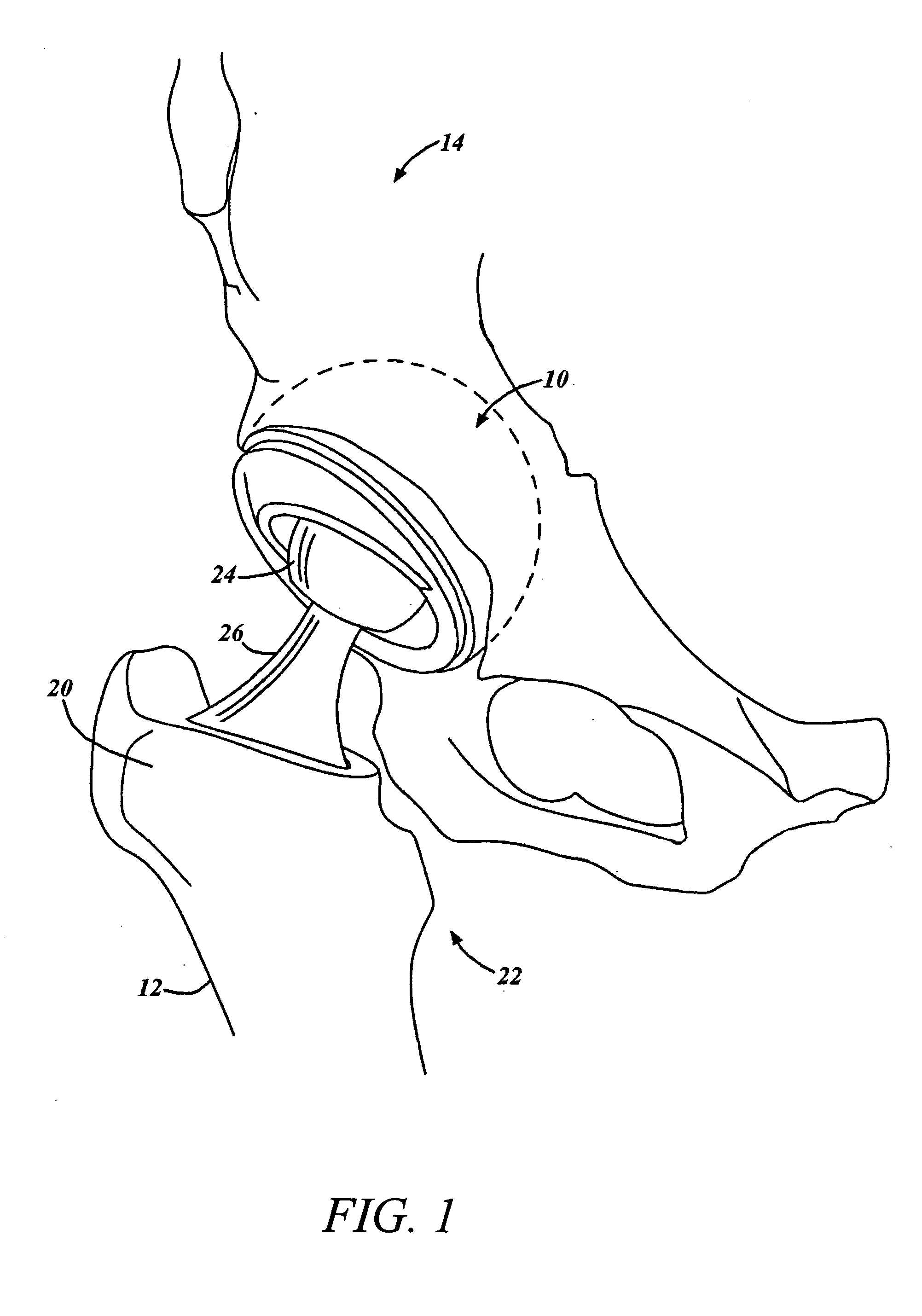
[0020]FIG. 1 illustrates an anterior cross-sectional view of an example human hip having a femoral implant. The semi-circular shape of the acetabulum 10 can be seen. The upper leg bone, or femur 12, which can be seen just below the ilium 14, is the longest and strongest bone in the body. The upper end of the femur 12 is provided with a spheroidally shaped head, a neck, a greater trochanter 20, and a lesser trochanter 22.
[0021] Total hip replacement typically involves a complete internal dissection of the hip joint. The conventional surgical procedure used during total hip replacement involves making a surgical incision to provide an approach to the hip. Once the hip is exposed, the joint is dislocated so that the femoral head 16 and acetabular socket 10 can be accessed. The femoral head and neck are then dissected. Once the femoral head and neck have been removed, the femoral canal (the central core of the bone) is reamed so as to provide a cavity into which a femoral implant may b...
PUM
 Abstract
Description
Claims
Application Information