Hucklebone supporting-type artificial leg

a technology of artificial legs and hucklebones, which is applied in the field of artificial legs with hucklebones, can solve the problems of insufficient fixation between the artificial leg and the physical body, and insufficient fixation between the artificial leg and the thigh, so as to improve the wearability of the artificial leg and support the physical weight, improve the stability of the artificial leg wearing person, and improve the wearability of the artificial

Inactive Publication Date: 2005-05-12
IKEDA ISAO
View PDF9 Cites 4 Cited by
  • Summary
  • Abstract
  • Description
  • Claims
  • Application Information

AI Technical Summary

Benefits of technology

[0013] As described above, the present invention enables an installing characteristic of the artificial leg to be improved and a stable walking of the wearing person to be carried out by a method in which each of front and rear belt supporting units is attached to the front end and rear end of the saddle in such a way that they can be turned in an upward or downward direction, waist belts are connected to each of the upper ends of the front and rear belt supporting units and further installed around the waist of the artificial leg wearing person in such a way that they can be fastened and removably set. In addition, the artificial leg wearing characteristic can be further improved and a stable walking of the leg wearing person can be attained by a method wherein the end portions of the shoulder hanging bands are connected to the upper ends of the front and rear belt supporting units, and supported such that the saddle is hung at each of the shoulders of the artificial leg wearing person.
[0014] Further, a stable characteristic of the artificial leg supporting a physical weight can be increased and a walking state can be made more smooth by a method wherein the upper portion of the shaft is offset from the central connecting position of the saddle to the slant front side of the damaged or lost lower leg. In addition, the connecting part between the upper end of the shaft and the saddle is of a fastening structure using threads and the offset direction at the upper end of the shaft can be changed over between a right side and a left side to enable the artificial leg for a right foot and the artificial leg for a left foot to be applied in common. Further, it becomes possible to change over the offset direction at the foot part in response to a degree of training in walking after wearing the artificial leg and use the artificial leg separately for each of the right and left feet.

Problems solved by technology

However, in the case that the length of the thigh left in the damaged or lost lower leg is short, the artificial leg and the thigh are insufficiently fixed.
In addition, in the case that the lower leg is cut at the crotch articulation part, the artificial leg cannot be fixed to the thigh portion.
Under these cases, there occurred a problem that the artificial leg is insufficiently fixed to the physical body and the work for pulling up the rear artificial leg and moving it in a forward direction cannot be carried out smoothly during walking.
As a result, in the case that the thigh portion is left in a rearward direction during walking and the artificial leg is inclined in a rearward direction, the pelvis is simultaneously inclined and the upper half body is inclined forwardly or twisted to cause a walking attitude to become disturbed.
As a result, an attitude for supporting the upper physical body shows an unbalanced state at the right half and the left half, the attitude easily becomes a state in which the upper physical body moves to the normal lower leg, and the attitude of the upper physical body during walking is also easily disturbed.

Method used


Image

  • Hucklebone supporting-type artificial leg
  • Hucklebone supporting-type artificial leg
  • Hucklebone supporting-type artificial leg

Examples


Embodiment Construction

[0032] Referring now to the drawings, the preferred embodiment of the present invention will be described as follows.

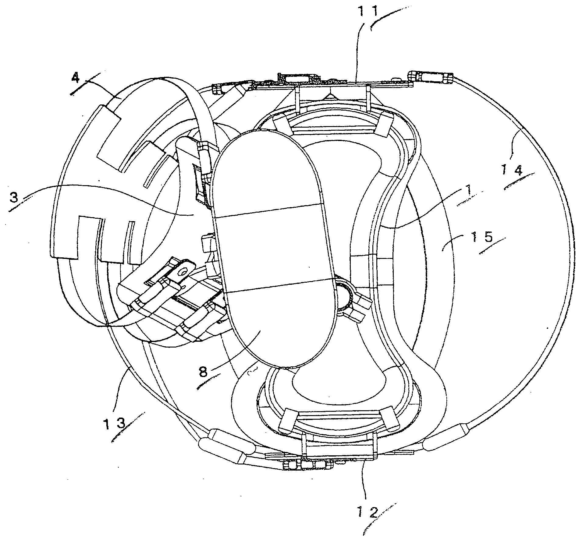
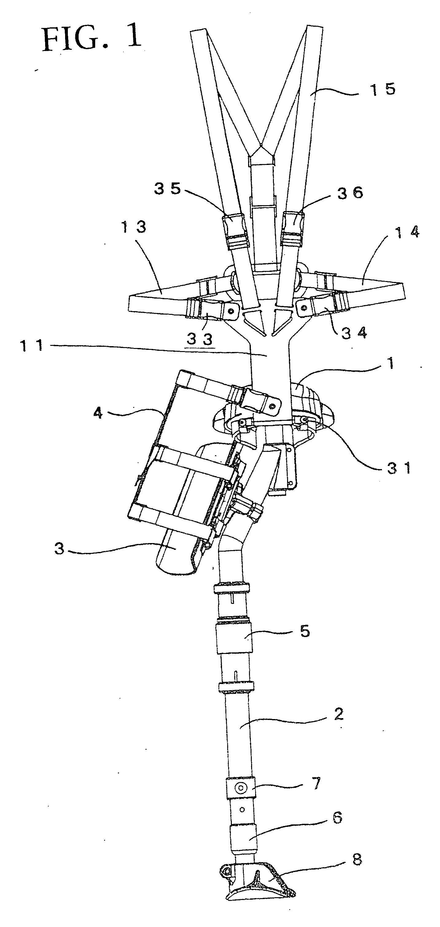
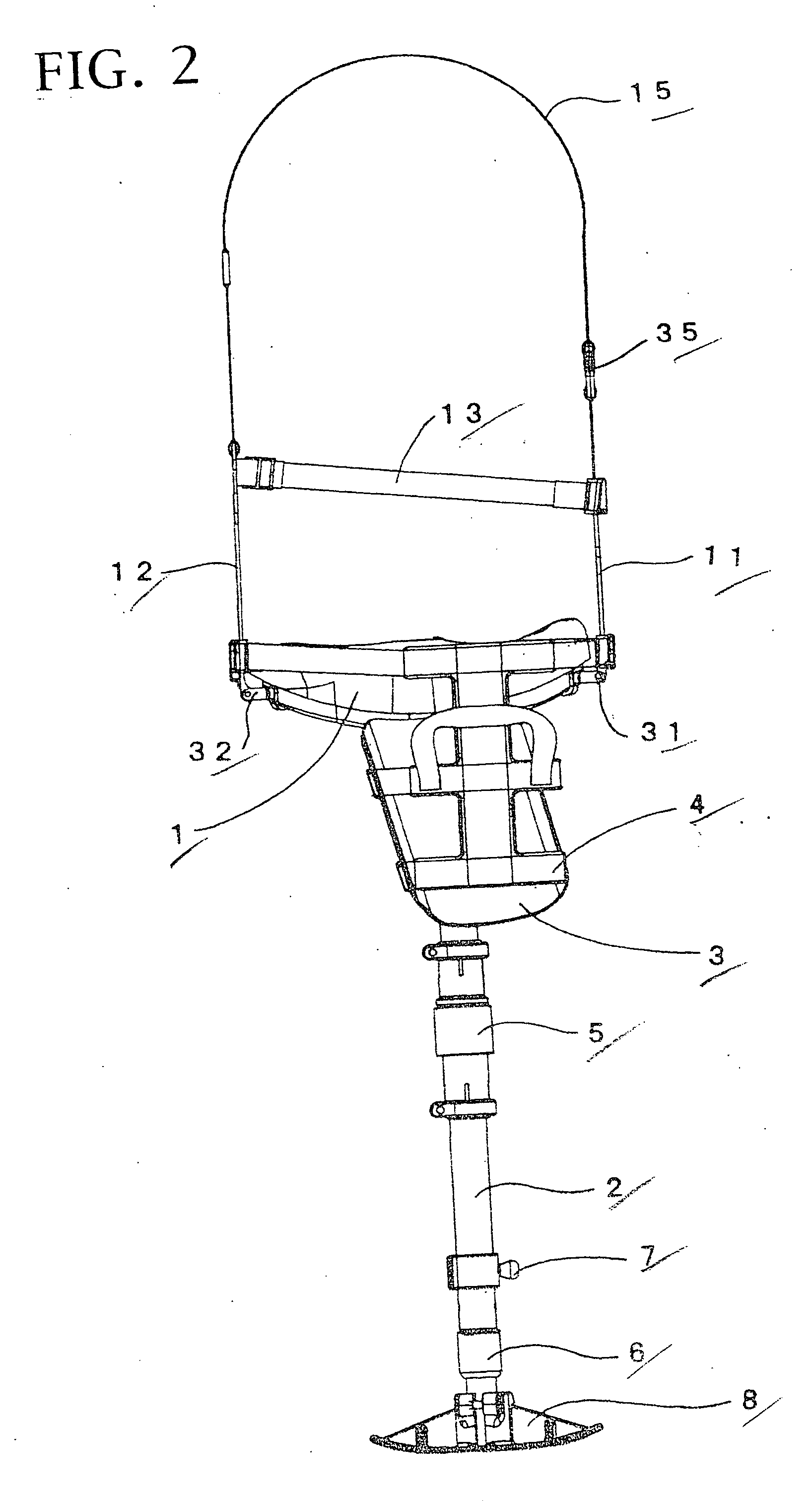
[0033] FIGS. 1 to 6 are views for showing a state in which the shoulder hanging band is connected to the hucklebone supporting-type artificial leg of the present invention. FIG. 1 is a front elevational view. FIG. 2 is a left side elevational view. FIG. 3 is a right side elevational view. FIG. 4 is a rear view. FIG. 5 is a top plan view. FIG. 6 is a bottom view. FIG. 7 is a left side elevational view for showing a state in which a shoulder-hanging band and a fastening band for fixing the thigh are removed from FIG. 2. FIG. 8 is a perspective view for showing a state in which a shoulder-hanging band is removed, and a waist belt and a fastening band for fixing the thigh are removed.

[0034] As shown in these figures, a shaft 2 is connected to a substantial central part of the lower surface of a saddle 1. At a location near the upper end of the shaft 2, the lower side of...


PUM


Abstract

This invention enables a smooth walking action to be carried out even in the case that a length of the thigh portion left in the damaged or lost lower leg is short or in the case that the lower leg is cut from the crotch articulation part and the thigh is lost. A hucklebone supporting-type artificial leg comprised of a saddle, a shaft suspended down at the lower surface of the saddle and having a substantial same length as that of a lower leg and a foot fixed to the lower end of the shaft, wherein the artificial leg comprises a front belt supporting unit attached at a front end of the saddle in such a way that it can be turned in a forward, upward and downward direction; a rear belt supporting unit attached at a rear end of the saddle in such a way that it can be turned in a rearward, upward and downward direction; and waist belts connected to each of the upper ends of the front and rear belt supporting units and installed around the waist of an artificial leg wearing person in such a way that the belts can be fastened to the waist and engaged with or disengaged from the waist. Further, there are provided shoulder hanging bands having ends connected to each of upper ends of the front and rear belt supporting units and installed in such a way that they can be fastened to and removably set to the shoulders of the artificial leg wearing person.

Description

BACKGROUND OF THE INVENTION [0001] 1. Field of the Invention [0002] This invention relates to the hucklebone supporting-type artificial leg so as to support a physical weight while arranging a saddle at the upper end of the artificial leg and abutting it against the crotch. [0003] 2. Description of the Related Art [0004] As the hucklebone supporting-type artificial leg for use in supporting a physical weight by the hucklebone while arranging a saddle against the upper end of the artificial leg and abutting it against the crotch and at the same time for fixing the thigh left at the lost lower leg, “the artificial leg” described in Patent Document 1 or “the saddle type crutches” described in Patent Document 2 is provided. These units enabled a person lost the lower leg or injured due to accident, mine and disease or the like to install the artificial leg and walk at an early stage where the injury portion is not completely healed because the saddle is abutted against the crotch to sup...

Claims


Application Information

Patent Timeline
Patent Type & Authority Applications(United States)
IPC IPC(8): A61F2/00A61F2/50A61F2/60A61F2/66A61F2/78
CPCA61F2/60A61F2/78A61F2002/30434A61F2002/30504A61F2002/5039A61F2220/0041A61F2002/6614A61F2002/7862A61F2002/7875A61F2002/7881A61F2220/0025A61F2002/5084A61F2002/30433A61F2002/305
Inventor IKEDA, ISAO
Owner IKEDA ISAO
Why Eureka
Try Eureka