Supercharge Your Innovation With Domain-Expert AI Agents!

Organic rankine cycle system with shared heat exchanger for use with a reciprocating engine

a technology of heat exchanger and rankine cycle, which is applied in the direction of steam engine plants, steam accumulators, hot gas positive displacement engine plants, etc., can solve the problems of commercial engines rejecting a large percentage of their waste heat, and atmospheric emissions such as nox and particulates can be an issue, so as to achieve the effect of increasing the temperatur

Active Publication Date: 2005-05-19
NANJING TICA AIR CONDITIONING CO LTD
View PDF32 Cites 19 Cited by
  • Summary
  • Abstract
  • Description
  • Claims
  • Application Information

AI Technical Summary

Benefits of technology

The invention relates to a system for improving the efficiency of a reciprocating engine by using staged heat exchangers to cool the engine and preheat the working fluid of an organic rankine cycle. The system replaces the usual heat exchanger apparatus with a set of heat exchangers wherein the heat is transferred to an ORC fluid, with the temperatures being progressively increased. The invention also provides for the sharing of a single heat exchanger that simultaneously receives heat from the engine coolant and from the engine oil sump, and transfers the heat to an ORC working fluid. The flow of engine coolant and engine oil is made to flow in one direction within a heat exchanger and the ORC fluid is made to flow in a counterflow direction. The invention can be modified and constructed in different ways without changing the main idea and scope of the invention.

Problems solved by technology

However, atmospheric emissions such as nitrous oxides (NOx) and particulates can be an issue with reciprocating engines.
However, commercial engines reject a large percentage of their waste heat through intake after-coolers, coolant jacket radiators, and oil coolers.

Method used


Image

  • Organic rankine cycle system with shared heat exchanger for use with a reciprocating engine
  • Organic rankine cycle system with shared heat exchanger for use with a reciprocating engine
  • Organic rankine cycle system with shared heat exchanger for use with a reciprocating engine

Examples


Embodiment Construction

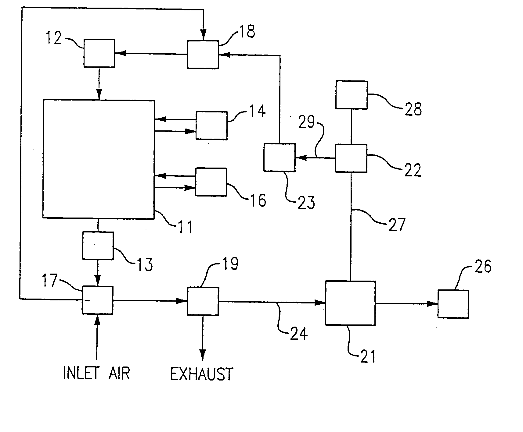
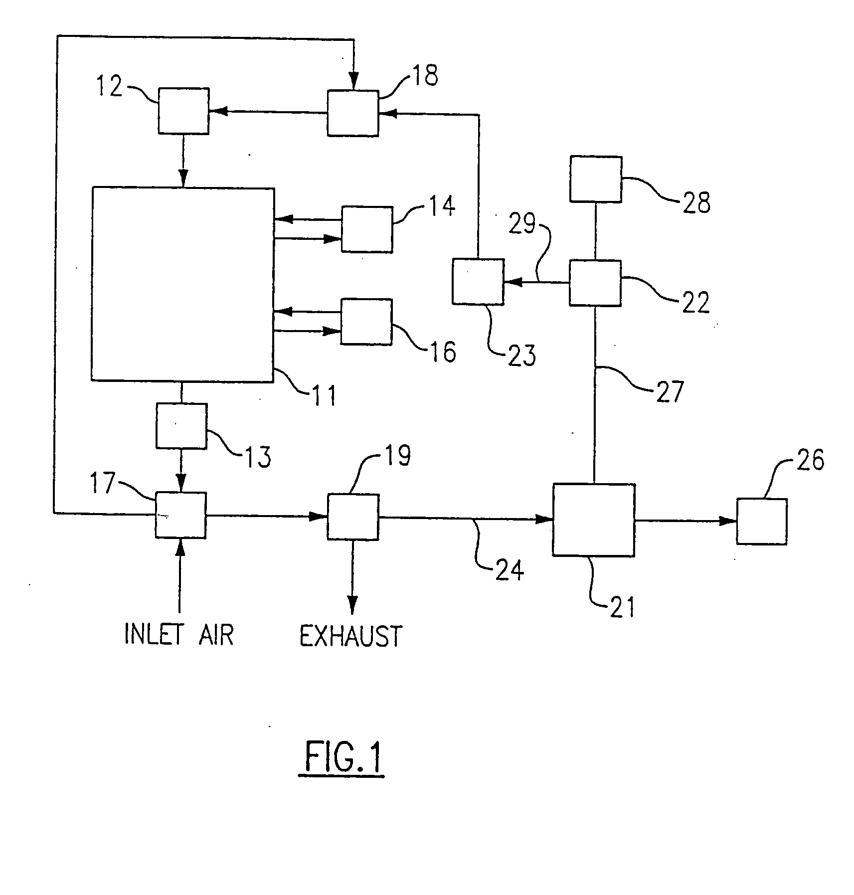
[0016] Referring now to FIG. 1, there is shown a reciprocating engine 11 of the type which is typically used to drive a generator (not shown) for purposes of providing electrical power for consumer use. The engine 11 has an air intake section 12 for taking in air for combustion purposes and an exhaust 13 which may be discharged to the environment, but is preferably applied to convert a portion of the energy therein to useful purposes. The engine 11 also has a plurality of heat exchangers with appropriate fluids for maintaining the engine 11 at acceptable operating temperatures.

[0017] One of the heat exchangers is a replacement heat exchanger 14 that transfers heat from a liquid coolant that is circulated in heat exchange relationship with the portion of the engine where combustion occurs, to an ORC working fluid. That is, the typical engine coolant-to-ambient air radiator of the reciprocating engine is replaced with a liquid-to-liquid (i.e. engine coolant-to-organic working fluid) ...


PUM


Abstract

In order to effectively extract the waste heat from a reciprocating engine, the normal heat exchanger components of an engine are replaced with one or more heat exchangers which have the motive fluid of an organic rankine cycle system flowing therethrough. With the heat transfer in the plurality of heat exchangers, the engine is maintained at a reasonable cool temperature and the extracted heat is supplied to an ORC turbine to generate power. The heat is derived from a plurality of sources within the reciprocating engine, and at least two of those sources have their fluids passing through the same heat exchanger. In one embodiment, the engine coolant and the engine lubricant pass through the heat exchanger in the same direction, and the ORC motive fluid passes therethrough in a counterflow relationship.

Description

BACKGROUND OF THE INVENTION [0001] This invention relates generally to waste heat recovery systems and, more particularly, to an organic rankine cycle system for extracting heat from a reciprocating engine. [0002] Power generation systems that provide low cost energy with minimum environmental impact, and which can be readily integrated into the existing power grids or which can be quickly established as stand alone units, can be very useful in solving critical power needs. Reciprocating engines are the most common and most technically mature of these distributed energy resources in the 0.5 to 5 MWe range. These engines can generate electricity at low cost with efficiencies of 25% to 40% using commonly available fuels such as gasoline, natural gas or diesel fuel. However, atmospheric emissions such as nitrous oxides (NOx) and particulates can be an issue with reciprocating engines. One way to improve the efficiency of combustion engines without increasing the output of emissions is ...

Claims


Application Information

Patent Timeline
Patent Type & Authority Applications(United States)
IPC IPC(8): F01K23/06F01K25/08
CPCF01K23/065
Inventor RADCLIFF, THOMAS D.BIEDERMAN, BRUCE P.
Owner NANJING TICA AIR CONDITIONING CO LTD
Features
  • R&D
  • Intellectual Property
  • Life Sciences
  • Materials
  • Tech Scout
  • Unparalleled Data Quality
  • Higher Quality Content
  • 60% Fewer Hallucinations
Learn More