Variable trajectory kit for a ball pitching mechanism

Inactive Publication Date: 2005-05-19
UNIFIED SOLUTIONS
View PDF10 Cites 19 Cited by
  • Summary
  • Abstract
  • Description
  • Claims
  • Application Information

AI Technical Summary

Benefits of technology

[0003] Pitching machines are powerful and versatile training tools for athletes of all ages and skill levels. Developing players benefit from the safety and predictability of a ball being repeatedly delivered within t

Problems solved by technology

While these basic pitching machines are well suited for practicing the principle elements of a sport, they are all too often lacking in the ability to simulate actual game situations, such as high/low pitches and those that are to the inside or outside of the strike zone.
On one hand it is advantageous to consistently place the ball within a designated zone to perfect a technique, however this is an obvious contradiction to actual play where the trajectory and azimuth of the ball is relatively inconsistent and unpred

Method used


Image

  • Variable trajectory kit for a ball pitching mechanism
  • Variable trajectory kit for a ball pitching mechanism
  • Variable trajectory kit for a ball pitching mechanism

Examples


Embodiment Construction

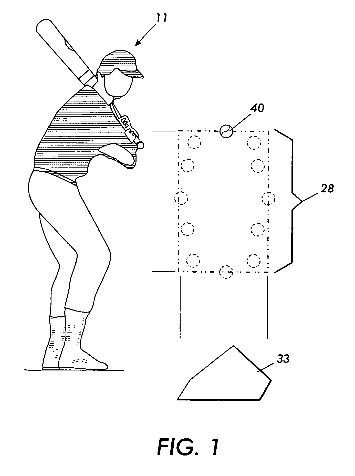
[0023] Referring to the drawings, in FIG. 1 the strike zone 28 is generally considered to be within an area immediately above home plate 33, where the upper limit thereof is a horizontal line at the midpoint between the top of the shoulders and the waist of batter 11, and the lower limit being a point extended from the knees of batter 11. Ball 40 is preferably presented within an elliptical pattern having both the minor and major axis within strike zone 28

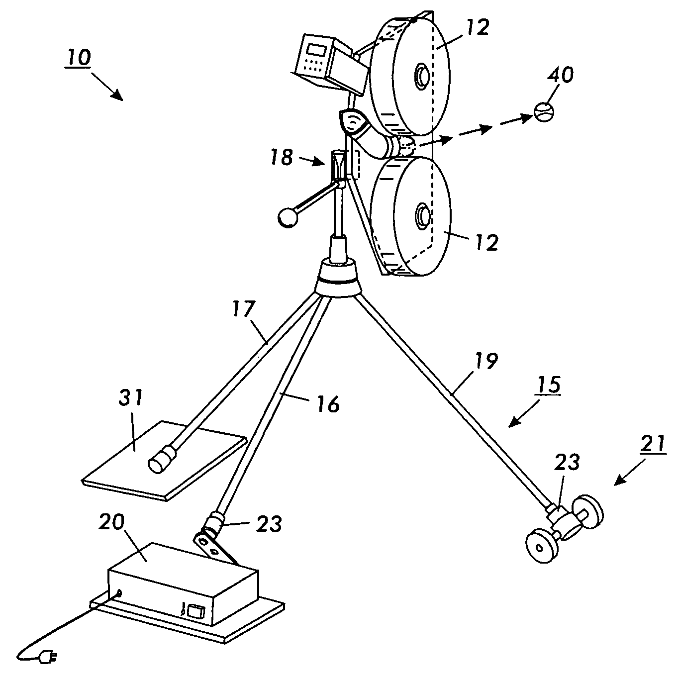
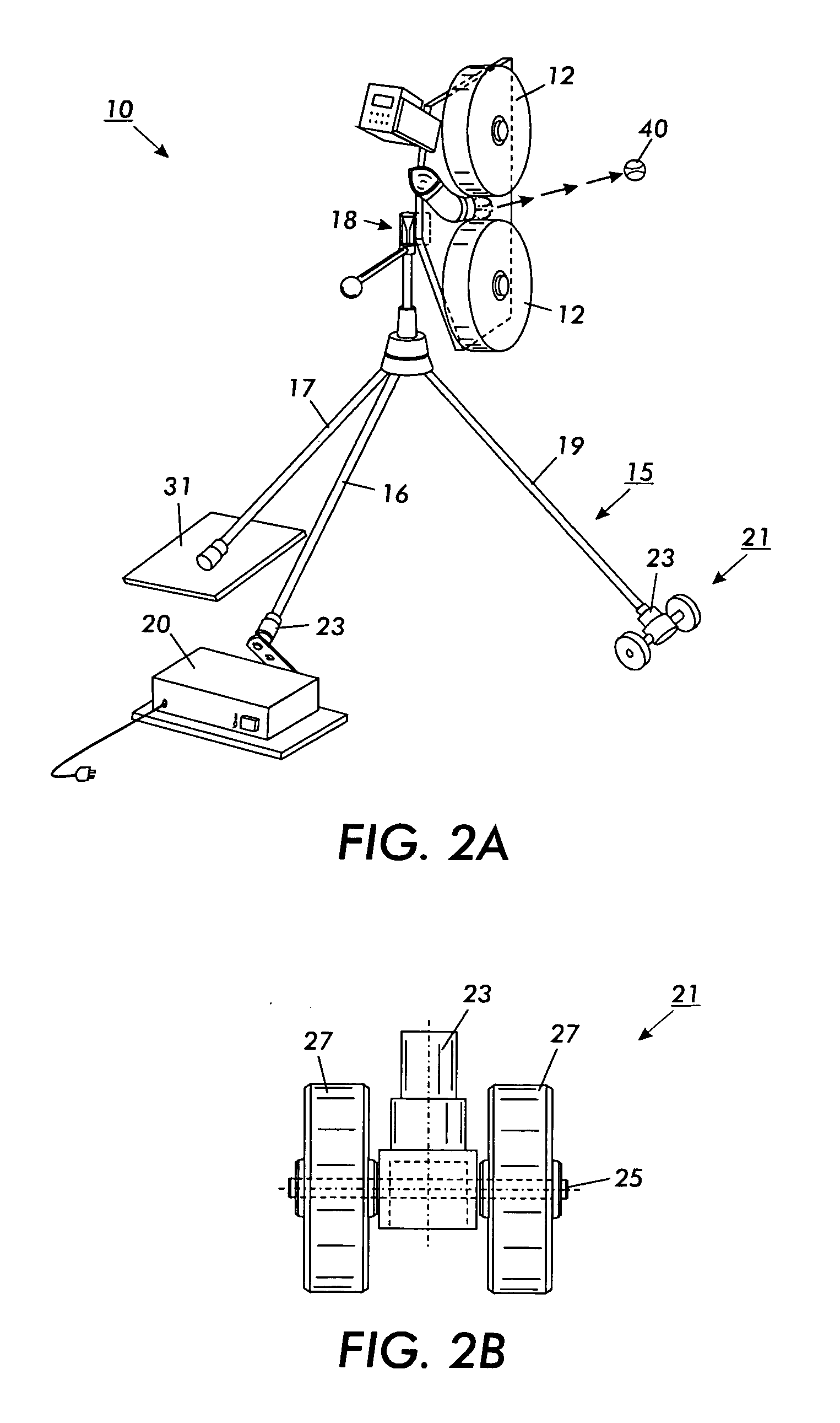
[0024] Now in FIG. 2A a typical ball propelling machine 10, having a pair of variable speed pitching wheels 12, whereas the constructed and operated is well known within the art. The ball pitching machine 10 may comprise a variety of configurations capable of delivering a ball or similar projectile to a target including belts, a pneumatic cannon or an arm to impart a propelling force to ball 40. Machine 10, which is an embodiment designed to throw ball 40 at a variable speed, is generally supported by triangular base 15 forming a t...


PUM


Abstract

The present invention is a method and apparatus for use with a ball throwing machine (e.g., baseball/softball pitching machines, tennis ball serving machines and the like) that may be employed for practice at hitting and/or catching balls thrown. In many conventional systems, such machines have a fixed position and are unable to vary the direction (horizontal) or angle (vertical) at which a ball is thrown. The present invention provides a simple, cost-effective device by which conventional machines may be adapted to provide randomly variable movement of the machine so as to enable a ball to move about a target location in order to simulate a competitive environment.

Description

CROSS REFERENCE TO RELATED APPLICATIONS [0001] This application claims the benefit of U.S. Provisional Application Ser. No. 60 / 520,024, filed on Nov. 14, 2003 and U.S. Provisional Application Ser. No. 60 / 558,837, filed on Apr. 2, 2004, which are hereby incorporated by reference. [0002] This invention relates generally to a throwing or pitching machine used in athletics for the practice of various ball dependant sports, such as baseball, football, tennis and the like, and more particularly to an improvement in the nature of a kit containing a mechanism to modify the trajectories of balls pitched or thrown by such machines.BACKGROUND AND SUMMARY OF THE INVENTION [0003] Pitching machines are powerful and versatile training tools for athletes of all ages and skill levels. Developing players benefit from the safety and predictability of a ball being repeatedly delivered within the center of the strike zone and thereby allowing the inexperienced athlete to work on swing mechanics under co...

Claims


Application Information

Patent Timeline
IPC IPC(8): A63B69/40A63B71/02F41B4/00
CPCA63B69/40F41B4/00A63B71/023A63B69/406
Inventor HUDSON, DAVID H.JORDAN, GARYCROMWELL, SAMUEL H.TUCKER, ALAN F.
Owner UNIFIED SOLUTIONS
Why Eureka
Try Eureka