Solar energy collector for hot water

a solar energy and collector technology, applied in the direction of collector casings, sustainable buildings, light and heating equipment, etc., can solve the problems of failure to anticipate the use of extended side panels, the inability to provide positioning and retention means for the supports, and the cost of higher system efficiency

Inactive Publication Date: 2005-05-19
NIEDERMEYER WILLIAM P
View PDF4 Cites 12 Cited by
  • Summary
  • Abstract
  • Description
  • Claims
  • Application Information

AI Technical Summary

Benefits of technology

[0005] For higher solar insolation, frames to adjust for angular orientation and its beneficial effect on the amount of solar heat collected are well known, but present practice avoids adjustable framework for flat plate or concentrating designs at the expense of higher system efficiency.
[0009] The instant collector relies on the same operating principles as '037 and is an improvement thereof by defining a fabricated blank that folds into a collector panel having integral inside walls with vertical slots that locate and retain the parabolic supports and thus eliminates the separately molded frames and the additional components required by '037.

Problems solved by technology

For higher solar insolation, frames to adjust for angular orientation and its beneficial effect on the amount of solar heat collected are well known, but present practice avoids adjustable framework for flat plate or concentrating designs at the expense of higher system efficiency.
Prior art, U.S. Pat. No. 4,190,037 describes use of corrugated material for reflector surface supports but fails to anticipate use and folding of extended side panels to provide positioning and retention means for the supports.

Method used


Image

  • Solar energy collector for hot water
  • Solar energy collector for hot water
  • Solar energy collector for hot water

Examples


Embodiment Construction

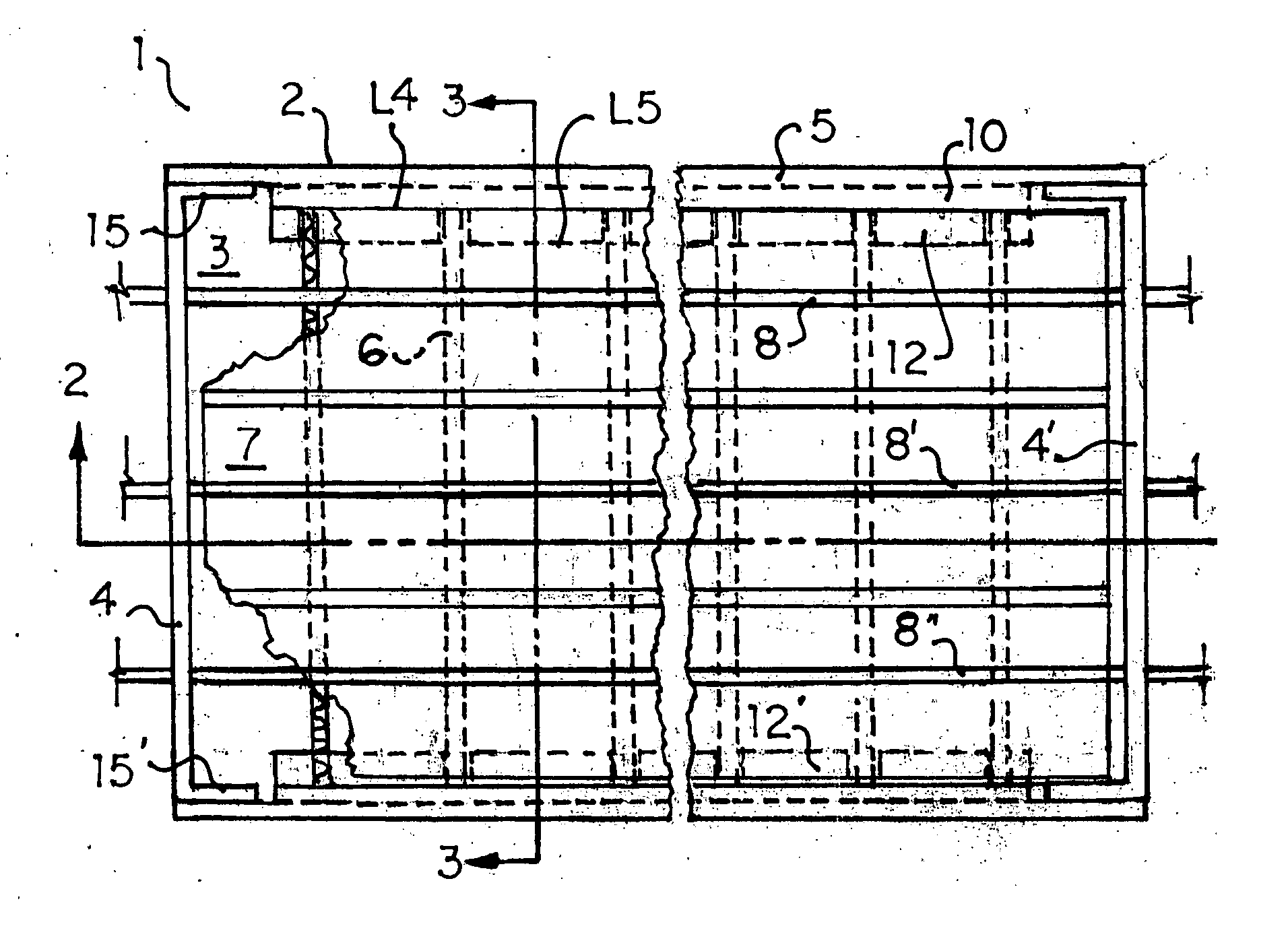
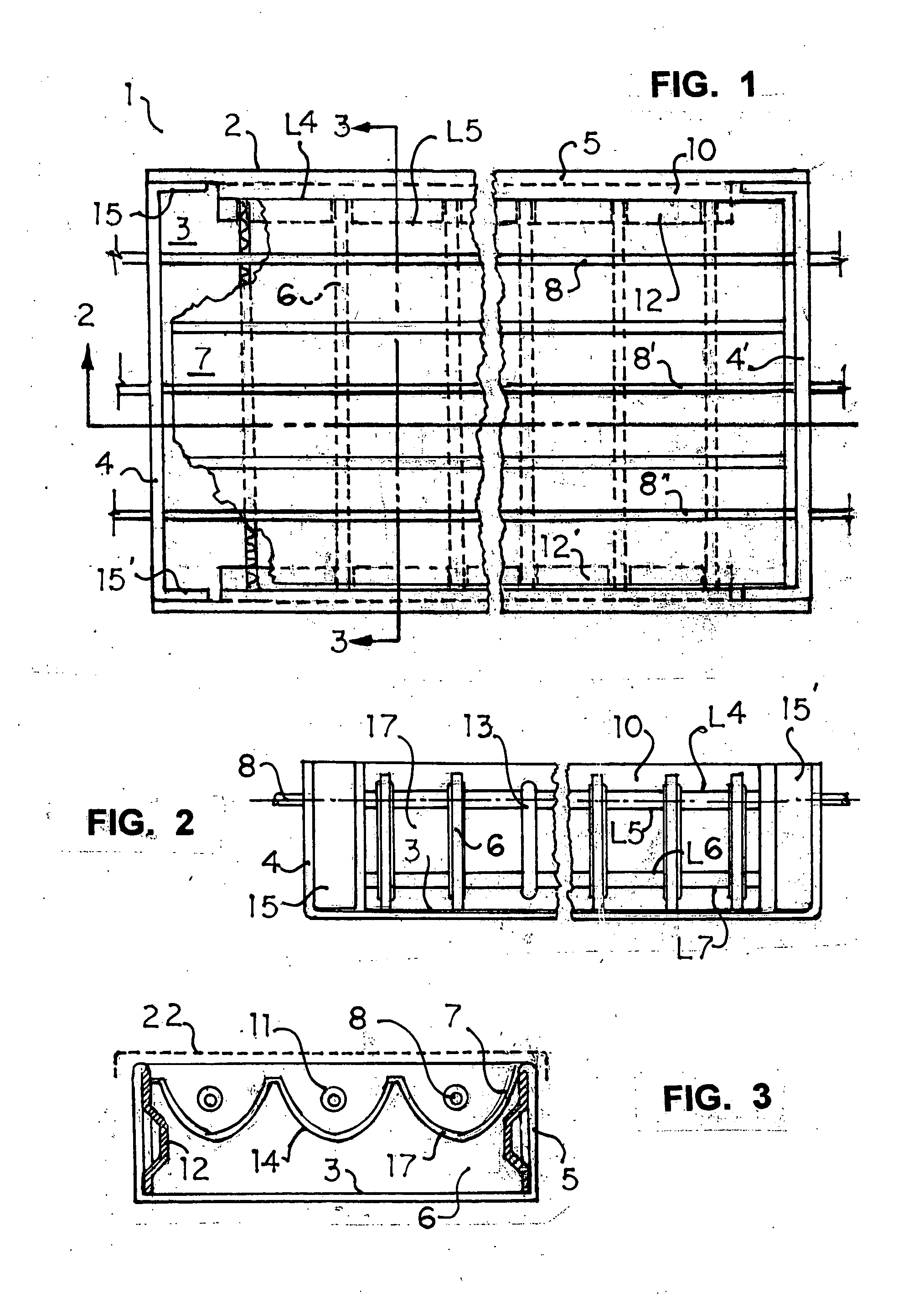
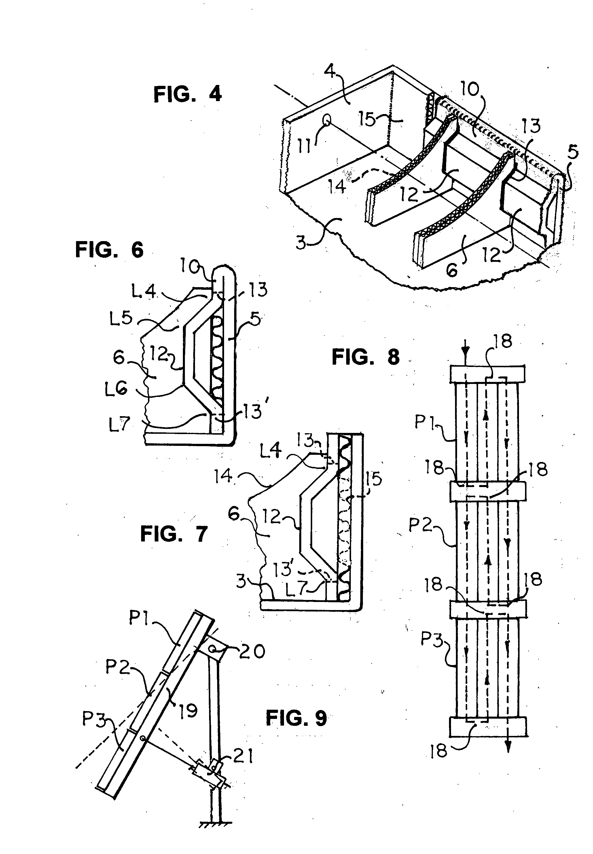
[0020] In FIG. 1, solar collector panel 1 consists of a frame having a bottom surface 3, end panels 4, 4′, side panels 5, 5′ and in the preferred embodiment, inwardly folded side panel extensions (10,10′ (see FIG. 6).

[0021] In FIG. 1, parabolic supports 6 (see FIGS. 3, 5) support reflector surface 7 (shown cutaway on the left side) and are held in slot cutouts 13 in the inside folded side panels 10,10′. Reflector surface 7 is bonded to an insulating substrate 17 (see FIG. 3) and focuses solar rays to absorbing collector conduit 8.

[0022] In FIG. 1, surface 7 extends between the inside folded panels 10,10′ and substantially between end panels 4, 4′.

[0023] In FIG. 2, the third slot 13 is shown without the support 6 to define its shape and length, noting that the upper slot end is above score / fold line L 4 and the bottom end is below score / fold line L7 to insure that ends of support 6 butt against surfaces of panels 10,10′.

[0024] In FIG. 3, absorber conduits 8 passes thru apertures ...


PUM


Abstract

A solar energy concentrating collector having a frame with bottom, end and side panels of corrugated material adapted to include secondary side panels that are folded inward and have vertical slots for containment of parabolic supports for a flexible reflective surface placed on top of the supports.. Frame end panels have apertures located on the parabolic focal line for connection of fluid conduits outside the frame. For arrangement in solar collector arrays, conduit apertures in end-to-end mounted collectors are aligned to receive a common absorber pipe that extends through and beyond a plurality of collector frames for external connections to conduits in the next adjacent parabolic reflective surface parallel to the first reflective surface in the same frame. Supports for the reflective surface have parabolic cutouts in the top portion and are processed as multiple side by side components in a corrugating machine. The preferred material is corrugated paperboard.

Description

BACKGROUND AND SUMMARY [0001] Presently, most solar collectors for hot water heating in residential and industrial applications include rigid frames (usually metal) with a conductive absorber plate having attached fluid conduits or a double plate absorber having internal fluid passages, plus glazing, gaskets, etc. to enclose the absorber within the frame. [0002] Flat plate collectors have the inherent ability to absorb indireect solar rays, for example during partially cloudy weather or days with thin cirrus type clouds, and are usually installed in arrays on rooftops with fixed slopes, or on framework with fixed slopes mounted on flat roofs of commercial buildings and factories. When arrays are mounted at ground level, fixed slopes are used. [0003] For low temperature fluid heating, parabolic concentrating collectors are not preferred since they require direct sunlight and changes in the mountng angle to keep solar rays focused on the fluid absorber pipe due to seasonal changes in ...

Claims


Application Information

Patent Timeline
Patent Type & Authority Applications(United States)
IPC IPC(8): F24J2/46F24S10/70F24S23/74
CPCF24J2/14F24J2/245Y02E10/45Y02B10/20Y02E10/44F24J2/4641F24S23/74F24S10/742F24S80/45Y02E10/40
Inventor NIEDERMEYER, WILLIAM P.
Owner NIEDERMEYER WILLIAM P
Why Eureka
Try Eureka