
Nestable catch basin assembly with removable debris trap
a technology of debris trap and catch basin, which is applied in the direction of sewer cleaning, sewage draining, ways, etc., can solve the problems of clogging or stopping, occupying much unnecessary storage and transit space, and the depth of the drainage conduit below the surface may vary from place to place, so as to improve the capture and retention of particulate debris and facilitate storage and transportation
- Summary
- Abstract
- Description
- Claims
- Application Information
AI Technical Summary
Benefits of technology
Problems solved by technology
Method used
Image

Examples
Embodiment Construction
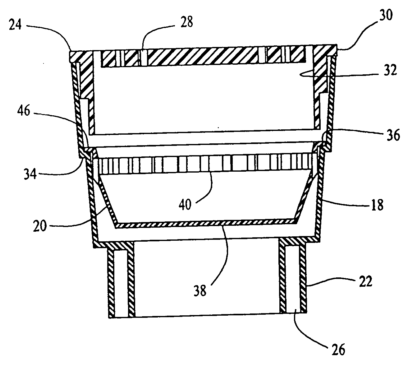
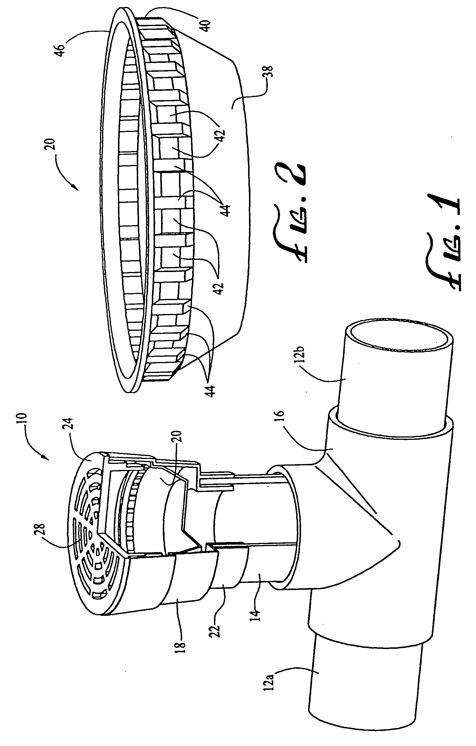
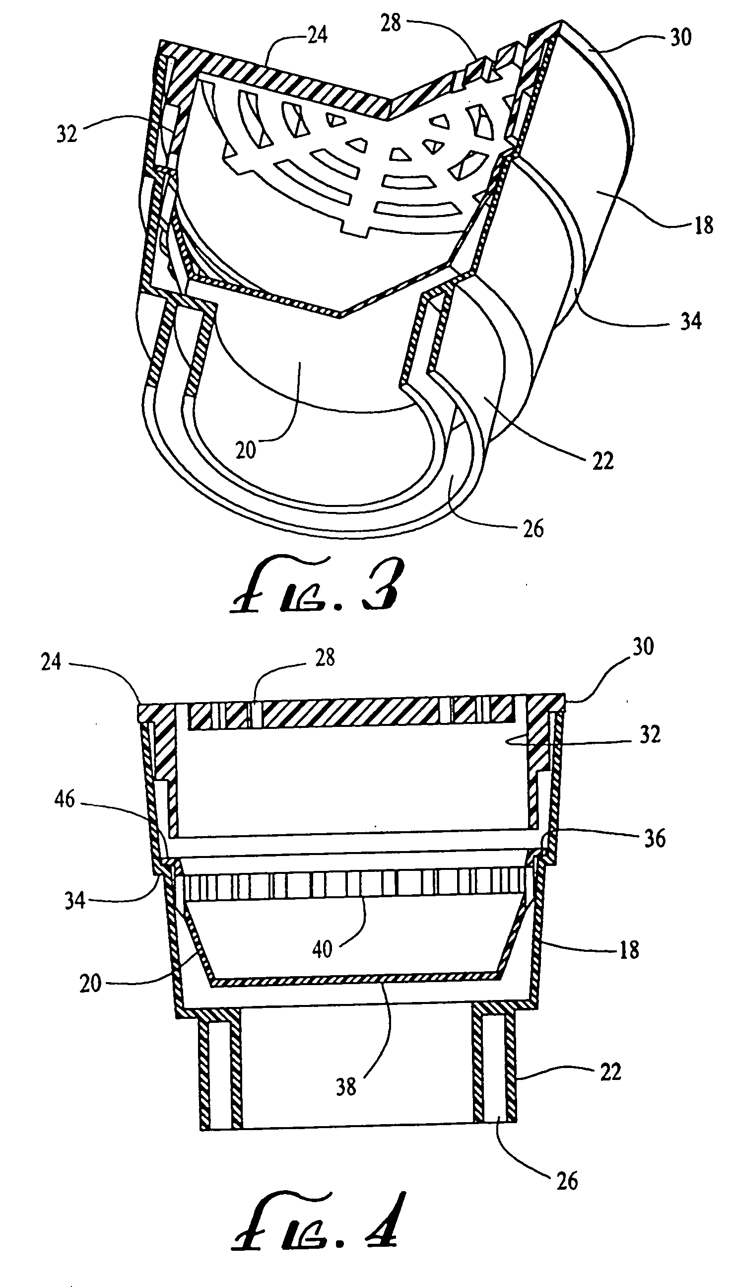
[0018] Turning first to FIGS. 1 through 4, a catch basin assembly 10, in accordance with a preferred embodiment of the present invention, is shown connected to a pair of conduits 12a, 12b by a vertical pipe or riser 14 and an inverted “T” fitting 16. The conduits 12a, 12b are of the type typically employed in a buried pipe drainage system. They are fluidly coupled to each other and to the riser 14 by the “T” fitting 16 by any conventional means well-known in the art. For example, the upstream conduit 12a is inserted into one horizontal leg of the “T” fitting 16, the downstream conduit 12b is inserted into the other horizontal leg of the “T” fitting, and the riser 14 is inserted into the upright (vertical) leg of the “T” fitting. The conduits 12a, 12 and the riser 14 may be secured to the “T” fitting 16 by any suitable means. For example, if these components are made of PVC tubing, they may be secured by any suitable adhesive.
[0019] The catch basin assembly itself comprises a recept...
PUM
 Abstract
Description
Claims
Application Information