Hand-held laser welding wand reflection shield

Inactive Publication Date: 2005-05-19
HONEYWELL INT INC
View PDF32 Cites 26 Cited by
  • Summary
  • Abstract
  • Description
  • Claims
  • Application Information

AI Technical Summary

Benefits of technology

[0008] The present invention provides a shield for a hand-held laser welding want that will reflect laser light reflected off a work piece surface away from the han

Problems solved by technology

Although programmable laser welding machines, such as that described above, are generally reliable, these machines do suffer certain drawbacks.
For example, a user may not be able to manipulate the laser light or work piece, as may be needed, during the welding process.
This can be problematic for weld processes that involve the repair or manufacture of parts having extensive curvature and / or irregular or random distributed defect areas.
However, because an operator holds the wand while welding a work piece, the operator's hand may be in close proximity to the work piece.

Method used


Image

  • Hand-held laser welding wand reflection shield
  • Hand-held laser welding wand reflection shield
  • Hand-held laser welding wand reflection shield

Examples


Embodiment Construction

[0019] Before proceeding with the detailed description, it should be appreciated that the following detailed description is merely exemplary in nature and is not intended to limit the invention or the application and uses of the invention. Furthermore, there is no intention to be bound by any theory presented in the preceding background or the following detailed description.

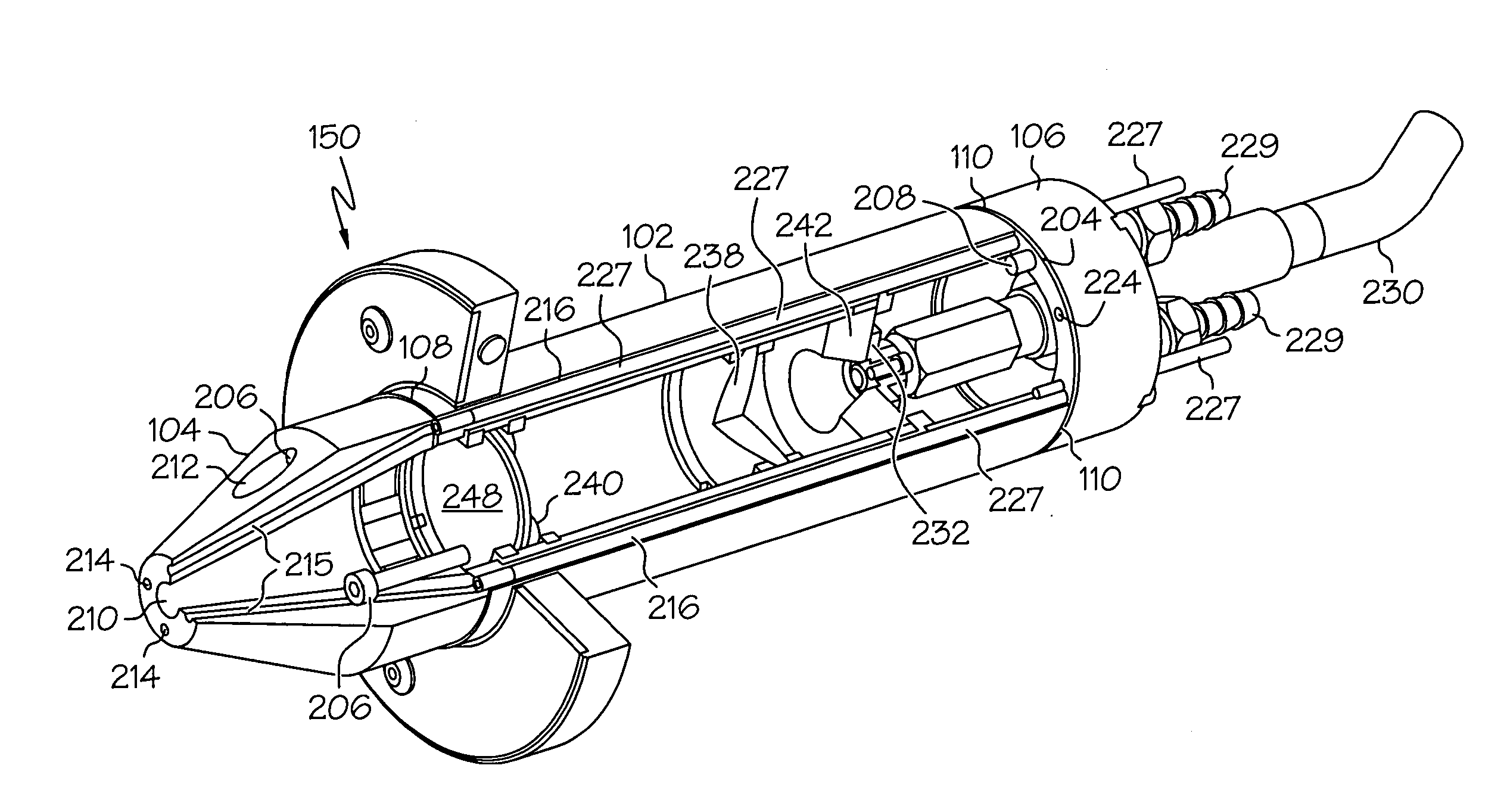
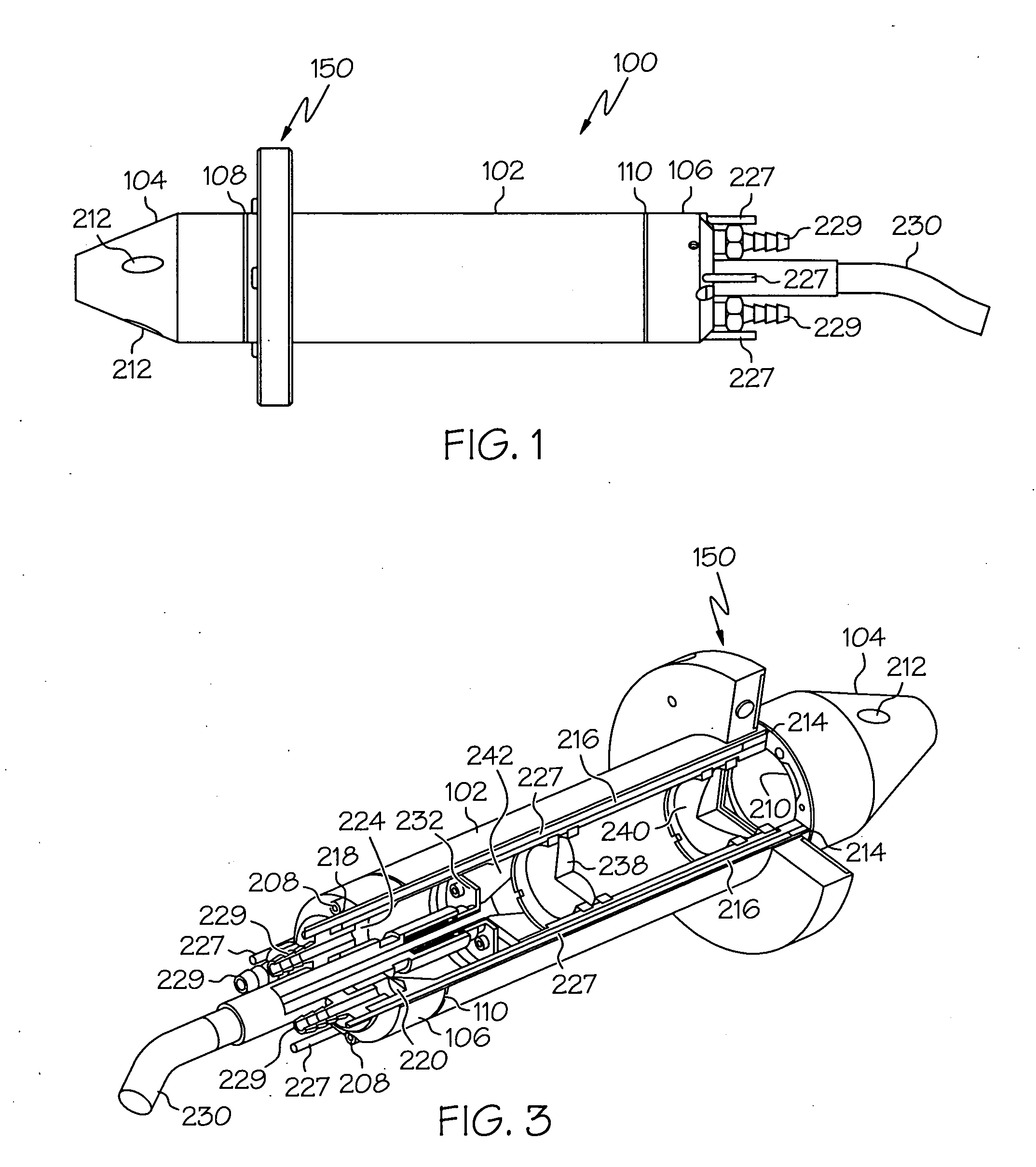
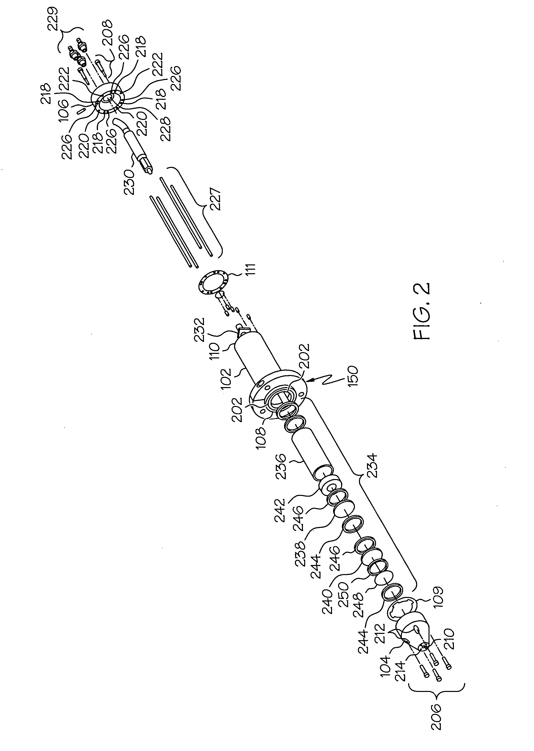
[0020] Turning now to the description, and with reference first to FIGS. 1-5, an exemplary hand-held laser welding wand 100 is shown, and includes a main body 102, a nozzle 104, and an end cap 106. The main body 102, which is preferably configured as a hollow tube, includes a first end 108 and a second end 110. As shown in FIGS. 2-5, the main body first 108 and second 110 ends each include a plurality of threaded openings 202 and 204, respectively. The threaded openings 202 in the main body first end 108 each receive a nozzle fastener 206 having mating threads, and which are used to couple the nozzle 104 to the ...


PUM

PropertyMeasurementUnit
Thermal propertiesaaaaaaaaaa
Proximity effectaaaaaaaaaa

Abstract

A hand-held laser welding wand includes a reflection shield that reflects laser light that is reflected off a work piece surface away from the hand of a user of the hand-held laser welding wand. The shield also reflects the thermal radiation transmitted from the work piece toward the wand during the weld process. This will help guard against a user of the wand absorbing laser light that may be reflected off the work piece, as well as significantly reduce any heat that might be transferred to the wand as a result of the reflected laser light.

Description

CROSS-REFERENCE TO RELATED APPLICATIONS [0001] This application is related to U.S. patent application Ser. No. 10 / 460,008, filed Jun. 12, 2003, which is a divisional of U.S. patent application Ser. No. 10 / 071,025, filed Feb. 8, 2002, which issued as U.S. Pat. No. 6,593,540, on Jul. 15, 2003.FIELD OF THE INVENTION [0002] The present invention relates to laser welding and, more particularly, to a hand-held laser welding wand that includes a reflection shield. BACKGROUND OF THE INVENTION [0003] Many components in a jet engine are designed and manufactured to withstand relatively high temperatures. Included among these components are the turbine blades, vanes, and nozzles that make up the turbine engine section of the jet engine. In many instances, various types welding processes are used during the manufacture of the components, and to repair the components following a period of usage. Moreover, various types of welding technologies and techniques may be used to implement these various...

Claims


Application Information

Patent Timeline
IPC IPC(8): B23K26/00B23K26/03B23K26/14B23K26/16B23K26/42
CPCB23K26/0096B23K26/03B23K26/427B23K26/16B23K26/1458B23K26/1462B23K26/706
Inventor BAKER, MARTIN C.RENTERIA, FEDERICOHUGHES, THOMAS M.TAYLOR, CLYDE R.
Owner HONEYWELL INT INC
Why Eureka
Try Eureka