Method of and apparatus for machining groove with laser beam

a technology of laser beam and groove, which is applied in the direction of manufacturing tools, connecting rod bearings, transportation and packaging, etc., can solve the problems of increasing facility costs, difficult to control the machining process for keeping and difficult to keep the depth of the groove substantially constant throughout the groove, etc., to achieve high accuracy

Inactive Publication Date: 2005-05-19
HONDA MOTOR CO LTD
View PDF6 Cites 38 Cited by
  • Summary
  • Abstract
  • Description
  • Claims
  • Application Information

AI Technical Summary

Benefits of technology

[0013] It is a general object of the present invention to provide a method of and an apparatus for machining a groove in an inner cylindrical surface of a workpiece highly accurately by applying a laser beam substantially perpendicularly to the inner cylindrical surface.

Problems solved by technology

However, since the laser beam is applied obliquely to the inner wall surface of the workpiece, it is difficult to control the machining process for keeping the depth of the groove substantially constant throughout the groove.
When the above machining process is employed to form a groove in the inner wall surface of the larger end hole of a connecting rod for use in a vehicular engine, and the larger end of the connecting rod is split from the groove into a shank and a cap, it is difficult to keep the depth of the groove substantially constant throughout the groove.
When a large impact force is set to split the connecting rod, however, the facility cost tends to increase and the yield of a connecting rod reduces as defective connecting rods are liable to be produced when split under the large impact force.

Method used


Image

  • Method of and apparatus for machining groove with laser beam
  • Method of and apparatus for machining groove with laser beam
  • Method of and apparatus for machining groove with laser beam

Examples


first embodiment

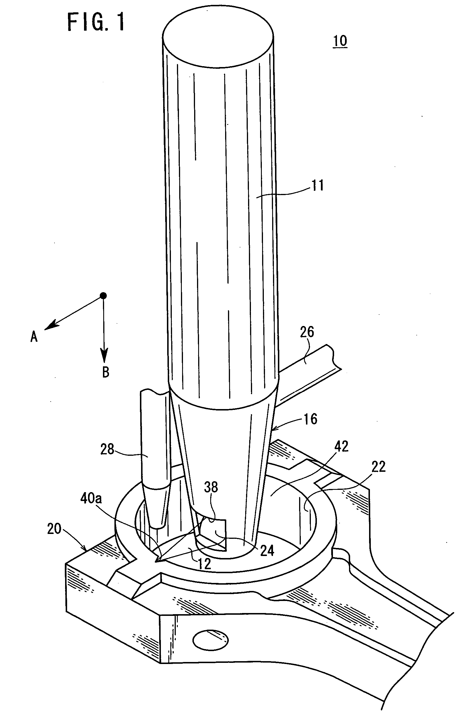
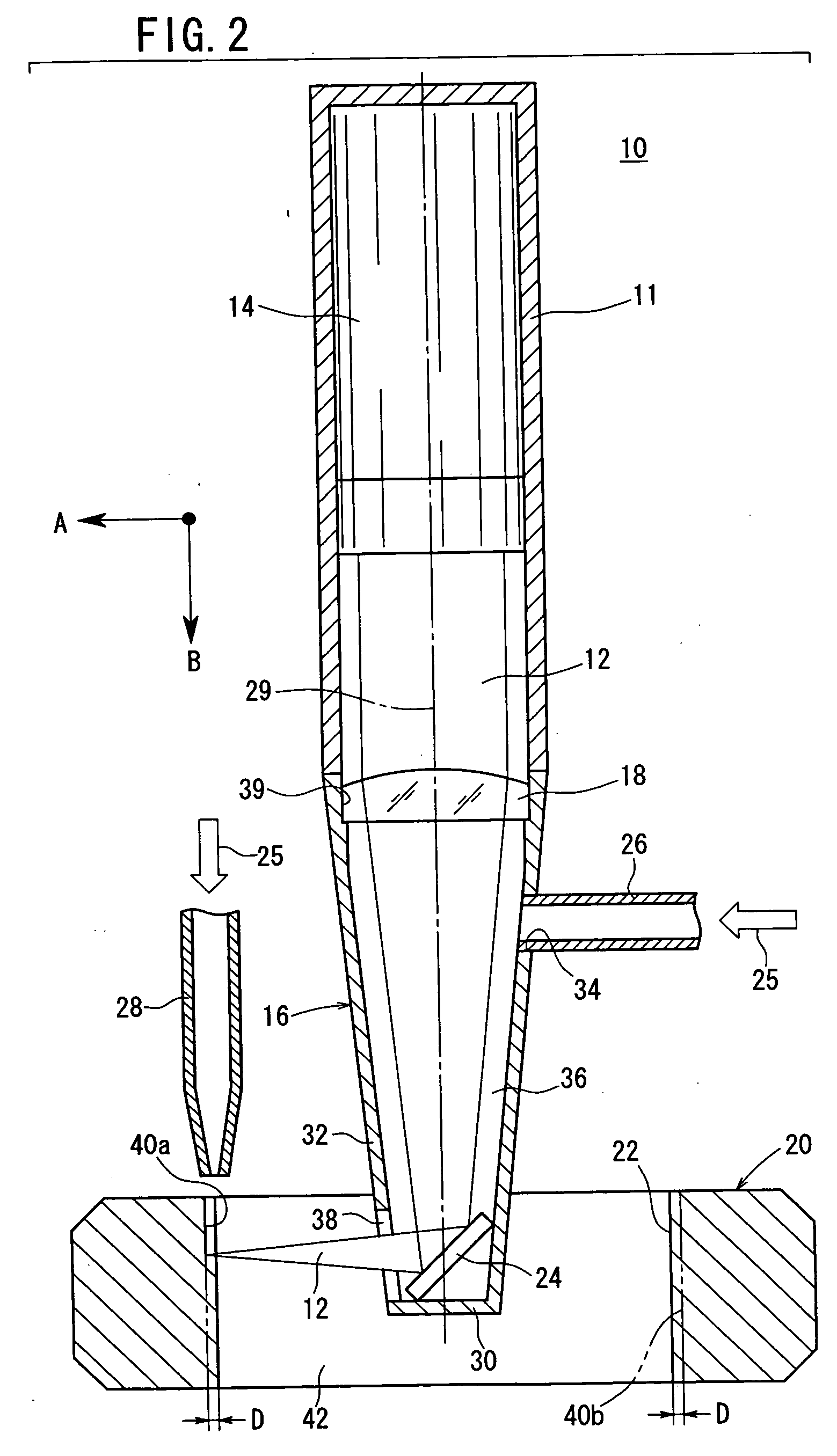
[0021]FIGS. 1 and 2 show an apparatus 10 for machining a groove with a laser beam (hereinafter referred to as “machining apparatus 10”) according to the present invention.

[0022] The machining apparatus 10 comprises a casing (body) 11 mounted on the end of an arm of an industrial articulated robot (e.g., a numerically-controlled apparatus), a laser oscillator 14 disposed in the casing 11 for emitting a laser beam 12, and a tubular head 16 disposed coaxially with the laser oscillator 14 and coupled to the lower end of the casing 11.

[0023] The machining apparatus 10 also has a condenser lens 18 held on the upper end of the head 16 for converging the laser beam 12 emitted from the laser oscillator 14 downwardly. A reflecting mirror 24 is fixedly mounted in the lower end of the head 16 and slanted at a certain angle to the vertical axis 29 of the head 16. The reflecting mirror 24 serves to reflect the laser beam 12 emitted from the laser oscillator 14 along the axis 29 into a direction ...

second embodiment

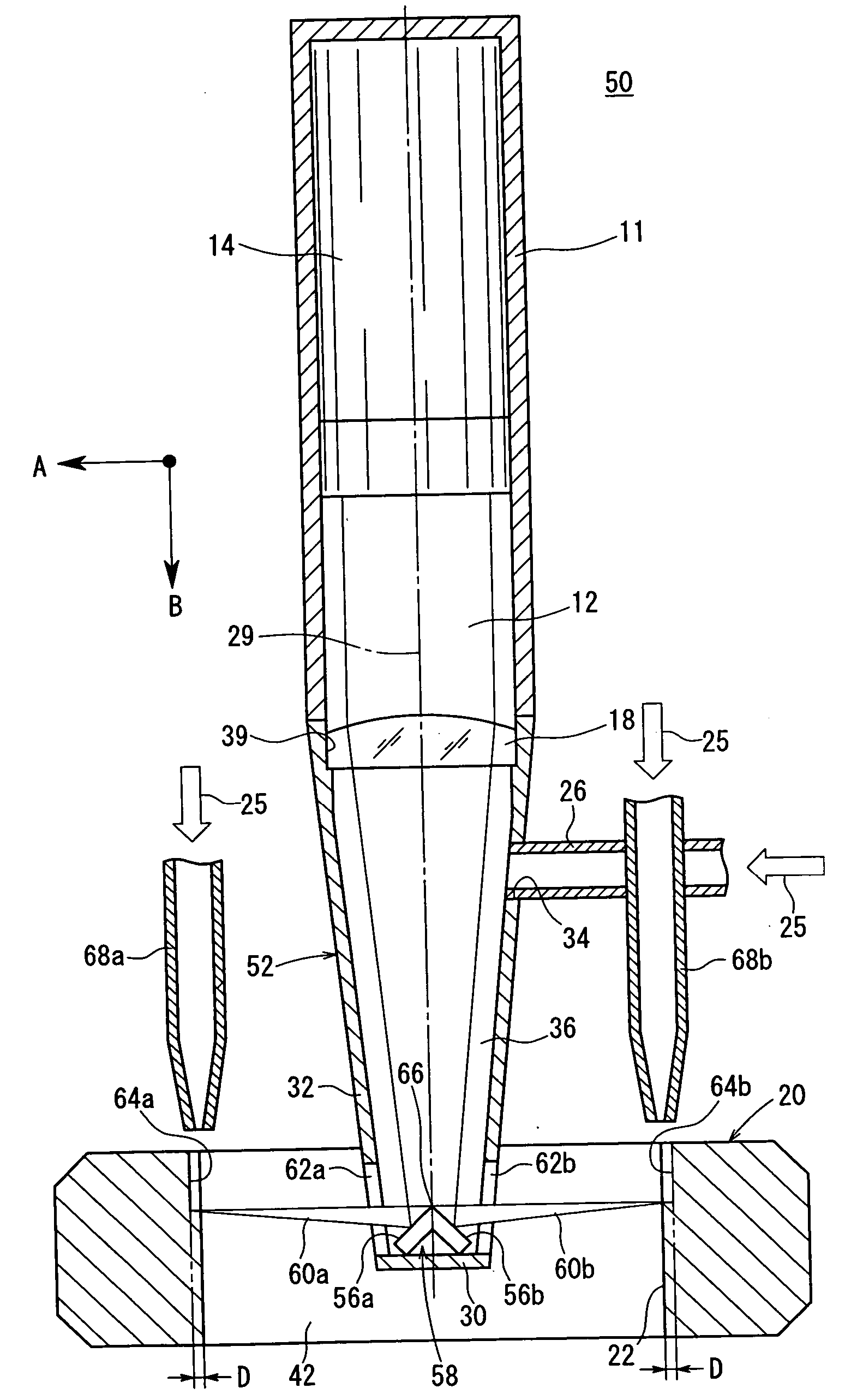
[0053] The machining apparatus 50 according to the present invention has a reflecting mirror 58 mounted on the bottom wall 30 of a head 52 in the form of a substantially conical tubular member. The reflecting mirror 58 has a pair of mirror surfaces 56a, 56b slanted at a certain angle symmetrically with respect to the axis 29 of the head 52. The mirror surfaces 56a, 56b face away from each other and confront respective emission holes 62a, 62b which are formed in the lower portion of the side wall 32 of the head 52 in diametrically opposite relation to each other. The reflecting mirror 58 divides the laser beam 12 emitted from the laser oscillator 14 into two beams 60a, 60b, which are applied through the emission holes 62a, 62b to the inner circumferential surface 22 of the workpiece 20, forming respective grooves 64a, 64b substantially simultaneously in the inner circumferential surface 22.

[0054] As shown in FIG. 4, the reflecting mirror 58, which is of a substantially triangular cro...


PUM

PropertyMeasurementUnit
depthaaaaaaaaaa
widthaaaaaaaaaa
frequencyaaaaaaaaaa

Abstract

A casing houses therein a laser oscillator for emitting a laser beam, and a tubular head is disposed coaxially with the laser oscillator and coupled to the casing. The laser beam emitted from the laser oscillator is converged by a condenser lens mounted on the head, and then reflected in a direction substantially perpendicular to the axis of the head by a reflecting mirror that is disposed in the head. The reflected laser beam is applied substantially perpendicular to the inner circumferential surface of a workpiece, forming grooves therein with the heat of the laser beam.

Description

BACKGROUND OF THE INVENTION [0001] 1. Field of the Invention [0002] The present invention relates to a method of and an apparatus for machining a straight groove in an inner cylindrical surface of a workpiece made of a metal material, by applying a laser beam thereto. [0003] 2. Description of the Related Art [0004] There have heretofore been known methods of and apparatus for applying a laser beam to a workpiece made of a metal material to cut or machine the workpiece with the heat generated by the applied laser beam. [0005] According to such laser beam machining method, as shown in FIG. 6 of the accompanying drawings, a laser beam 1 emitted from a laser oscillator is guided to a condenser lens 3 of an application nozzle 2 which is disposed coaxially with the laser oscillator. The laser beam 1 is converged by the condenser lens 3 and applied from the application nozzle 2 linearly to the surface of a workpiece 4 that is made of a metal material. The application nozzle 2 which applies...

Claims


Application Information

Patent Timeline
Patent Type & Authority Applications(United States)
IPC IPC(8): B23K26/067B23K26/10B23K26/16B23K26/36B23K26/38F16C9/00F16C9/04F16C33/10
CPCB23K26/0621B23K26/0643B23K26/067B23K26/0884B23K26/123B23K26/1405F16C33/108B23K26/1476B23K26/16B23K26/367B23K2201/006F16C9/045B23K26/147B23K26/364B23K26/142B23K26/0619B23K2101/006
Inventor MOMOSE, YASUO
Owner HONDA MOTOR CO LTD
Why Eureka
Try Eureka