Laser beam machining apparatus and corresponding method which employs a laser beam to pretreat and machine a workpiece

a laser beam and machining technology, applied in metal working equipment, manufacturing tools, welding/soldering/cutting articles, etc., can solve the problems of deterioration in machining quality, decrease in welding quality, and deterioration of work quality

Inactive Publication Date: 2000-03-21
MITSUBISHI ELECTRIC CORP
View PDF26 Cites 34 Cited by
  • Summary
  • Abstract
  • Description
  • Claims
  • Application Information

AI Technical Summary

Problems solved by technology

In this case, a work quality is deteriorated.
However, with the laser beam machining of FIG. 21 that uses the mixed gas as an assist gas, quality of the welding decreases if the thickness of the galvanized layer on the surface of the work is large.
FIG. 22 shows a cause of deterioration in machining quality in a laser beam cutting of the galvanized iron sheet.
If the main machining is done when the machined part is kept heated, heat input is excessive, so that there arises a state of self-burning in the cutting work and a structure of jointed parts is hypertrophied and embrittled in the welding work.
In case of adopting such a order to make the locuses coincide with each other, the device becomes complicated, expensive and of no practical use.
Moreover, the device using the partial reflector Mm and the total reflector Ms is only applicable to linear machining.
Though it is applicable to a galvanizing made of zinc that has a large absorption factor and a low melting point, it cannot be applied to a substance that has a low absorption factor and a high melting point.
Moreover, it cannot flexibly deal with the removal of coating materials having different properties.
If the absorption factor varies widely, the workpiece quality during cutting is deteriorated.
Also in welding the workpiece, if the absorption factor varies, a depth of penetration varies as well, so that a stable machining is impossible.
Moreover, if the oxide film becomes greater than a certain thickness, cracks are discontinuously produced by thermal shock in laser beam machining, so that the oxide film may exist at one position of the laser beam, and may not exist at another position.
If the absorption factor is varied, the work quality in cutting is deteriorated.
Also in welding work, if the absorption factor varies, a depth of penetration also varies, so that stable machining is impossible.
Furthermore, rust is produced on the soft steel material if it is left in a high humidity environment for a long time.
In laser cutting the part of material that is covered by rust there arises an abnormal combustion and the work quality is deteriorated.
If the absorption factor varies, the work quality in cutting is affected.
Also in welding, if the absorption factor varies, the width or depth of penetration varies, so that stable machining is impossible.
The larger work surface irregularity or surface roughness is, the more defects are caused in the work quality in the laser beam cutting.
The working speed is higher at a part that has a large surface roughness and absorption factor while the working speed is slower at a part that has a small surface roughness and absorption factor, so that work quality is not uniform.
Unless the work surface is perpendicular to the radiating direction of the laser beam, flow of the assist gas is disturbed in the cutting groove, thereby causing defective cutting.
Moreover, in the laser beam welding of a high reflectivity material, the laser beam is reflected in machining, so that stable machining work is not possible.

Method used


Image

  • Laser beam machining apparatus and corresponding method which employs a laser beam to pretreat and machine a workpiece
  • Laser beam machining apparatus and corresponding method which employs a laser beam to pretreat and machine a workpiece
  • Laser beam machining apparatus and corresponding method which employs a laser beam to pretreat and machine a workpiece

Examples


first embodiment

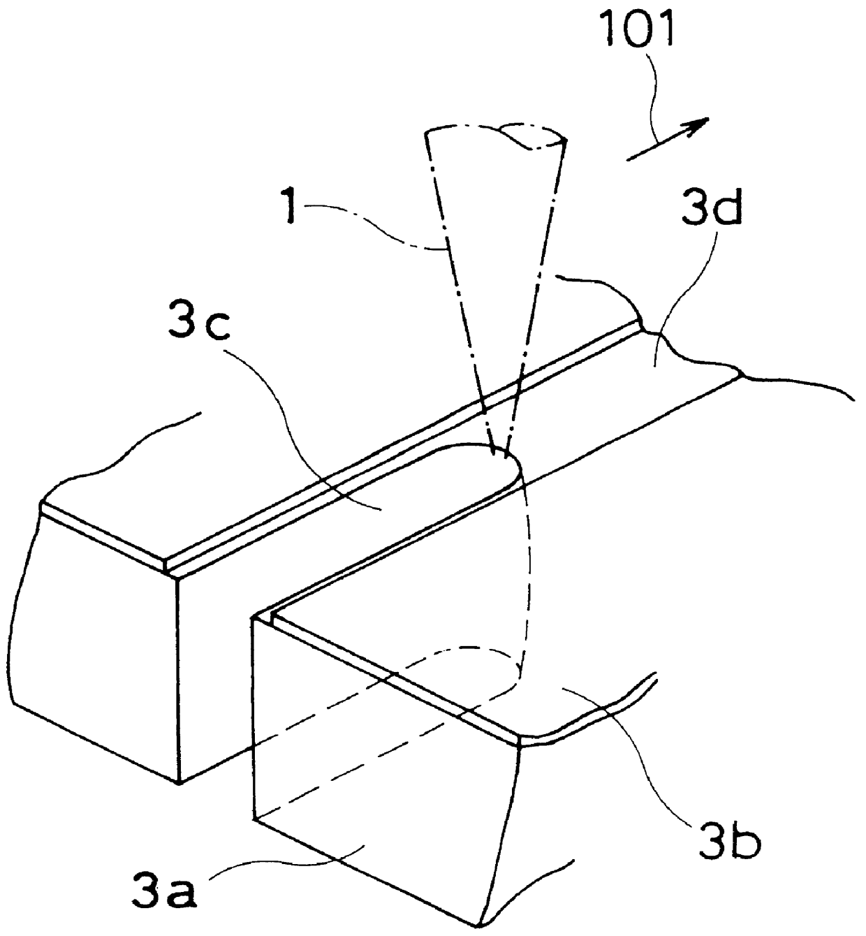
FIG. 1 is a perspective view showing a laser beam while it is cutting, after having removed a galvanized layer on a surface of a galvanized iron sheet by use of a first embodiment of an inventive laser beam machining method and an inventive device.

Referring to FIG. 1, the laser beam 1 is produced by a device, including laser beam oscillator, an optical system including lens and the like (not shown) and the laser beam 1 is irradiated onto the surface of a workpiece 3a, e.g. a galvanized iron sheet. The inventive method and device is applied to a variety of machining operations including cutting, welding, etc., although FIG. 1 shows the cutting of a workpiece. In FIG. 1, the workpiece 3a has a galvanized layer 3b removed by the laser beam 1, and a bare surface 3d is exposed and cut with a cut groove 3c.

The inventive laser beam machining device has improvements in its software structured in a microprocessor (not shown), and its detailed description of mechanical structure will be omitt...

second embodiment

The second embodiment is concerned with a laser be am welding while the first embodiment is concerned with a laser beam cutting. A similar device to that of the first embodiment is used to carry out the method of this embodiment, although a machining program is properly changed for a desired welding work.

The second embodiment has a preliminary machining step as a first stage, and the preliminary machining step is same as that of the first embodiment, and its detailed description is eliminated to avoid redundancy. Then, in a main machining step as a second stage, the laser beam 1 is irradiated onto a bare surface of the workpiece 3a, which is obtained by removing the galvanized layer 3b in the preliminary machining step, or a bead 3e provided in the workpiece 3a to weld it. At this time, an energy density is changed according to the main machining condition for the laser beam welding.

In the present embodiment, SECC of a plate thickness of 2 mm and a galvanizing amount of 50 g / m.sup.2...

third embodiment

The third embodiment uses a preliminary machining step as a first stage for treating the mill scale, though the preliminary machining step is similar to that of the first embodiment except it deals with the mill scale. Namely, the oxide film 3g is removed beforehand in the preliminary step for the following main step, in the same manner as removes the galvanized layer in the first embodiment. Then, in a main machining step as a second stage, the laser beam 1 is irradiated onto a clear surface of the workpiece 3a, which is obtained by removing the mill scale in the preliminary machining step, to cut it. The main machining step is same as that of the first embodiment, and its detailed description is eliminated to avoid redundancy.

Referring to FIG. 9, a thickness of the oxide film 3g on the workpiece 3a has an influence on a absorption factor of the laser beam 1. Generally, even when the thickness of the oxide film 1 is uneven, it is impossible to machine the workpiece 3a while recogni...


PUM

PropertyMeasurementUnit
thicknessaaaaaaaaaa
speedaaaaaaaaaa
widthaaaaaaaaaa

Abstract

A laser beam machining is carried out by irradiating beforehand the laser beam along a final locus for a main machining, under such a condition as to obtain an energy density for removing a galvanized layer as a surface substance of a work. Thereafter, the laser beam is irradiated to a bare area on which the zinc has been removed, while changing only the energy density according to a cutting condition to cut the work.

Description

1. Field of the InventionThis invention relates to a laser beam machining method and a device applicable thereto which carry out a cutting and welding, etc. of a workpiece made of metal by use of a laser beam, particularly to a laser beam machining method and a device that perform machining under actual machining conditions after having machined the workpiece under preliminary machining conditions so as to improve a surface state of the workpiece.2. Description of Background ArtGenerally, in a laser beam machining of a workpiece made of metal such as carbon steel, stainless steel or aluminum, a laser beam is irradiated onto the workpiece while injecting an assist gas thereto. When a workpiece having a surface coated with a substance of low melting point, an evaporating substance of low melting point possibly intrudes into a working area during the machining operation. In this case, a work quality is deteriorated.FIGS. 21 to 26 concern conventional cutting and welding techniques whic...

Claims


Application Information

Patent Timeline
Patent Type & Authority Patents(United States)
IPC IPC(8): B23K26/00B23K26/36B23K26/42B23K26/40B23K26/38B23K26/21B23K26/32B23K26/352C21D1/09
CPCB23K26/4005B23K26/401B23K26/402B23K26/421B23K26/40B23K26/60B23K2101/34B23K2103/04B23K2103/05B23K2103/10B23K2103/50B23K26/36B23K26/352
Inventor KANAOKA, MASARU
Owner MITSUBISHI ELECTRIC CORP
Why Eureka
Try Eureka