Laser machining machine

a laser machining machine and workpiece technology, applied in auxillary welding devices, laser beam welding apparatus, etc., can solve the problems of limited workpiece size, unsatisfactory machine structure, and partial material evaporate, and achieve high level of accuracy

Active Publication Date: 2011-05-26
CHARMILLES TECH SA +1
View PDF13 Cites 32 Cited by
  • Summary
  • Abstract
  • Description
  • Claims
  • Application Information

AI Technical Summary

Benefits of technology

[0004]The present invention enables the aforementioned drawbacks to be remedied with an architecture comprising at least three orthogonal linear axes and two mutually perpendicular rotary axes, enabling a laser machining head to be rotated about a horizontal axis and enabling the workpiece to be treated to rotate about a vertical axis. This structure provides a high level of accuracy since there is no variable flexion due to the weight and volume of the moving workpieces, and because the working conditions of the laser machining head remain essentially stationary. It should be noted that the laser source transmits its energy, i.e. the laser light, via an optical fibre unreeled along a cableway terminating at an optical output head defining the optical axis of the laser light beam which, at the end of its path, vaporizes the material. The laser machining machine proposed by the present invention is characterized especially by a particular arrangement of this optical output head that has to be rigidly attached to the frame or to the casing of the laser head and to remain integrally fastened to said frame or casing in order to ensure that the laser light beam is always stable, also during rotation of the laser head about the horizontal pivot axis.

Problems solved by technology

Material is removed by sudden heating of the area illuminated by the beam, causing a parcel of material to evaporate.
On one side, the workpiece to be machined is fixed on a worktable that pivots and moves along two perpendicular rotary axes B and C and one linear axis X. On the other side, the laser scanning head is supported by a linear shaft Z, the shaft itself moving along a final linear axis Y. Such a machine structure is not an ideal arrangement for machining heavy workpieces having a mass in excess of 200 kg, because of the flexibility of the cradle.
Moreover, the size of the workpieces is limited by the size of the cradle.

Method used


Image

  • Laser machining machine
  • Laser machining machine
  • Laser machining machine

Examples


Embodiment Construction

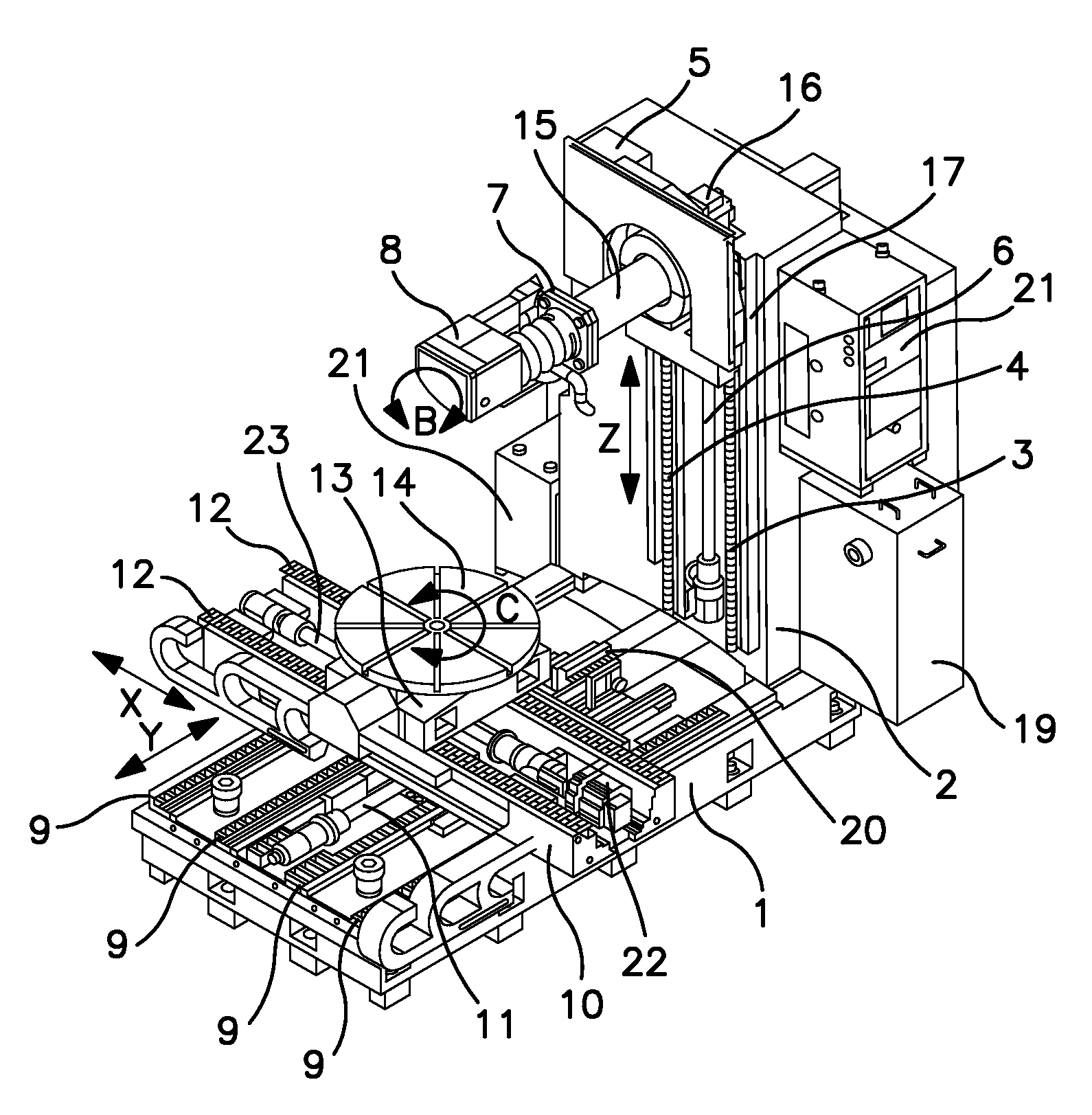
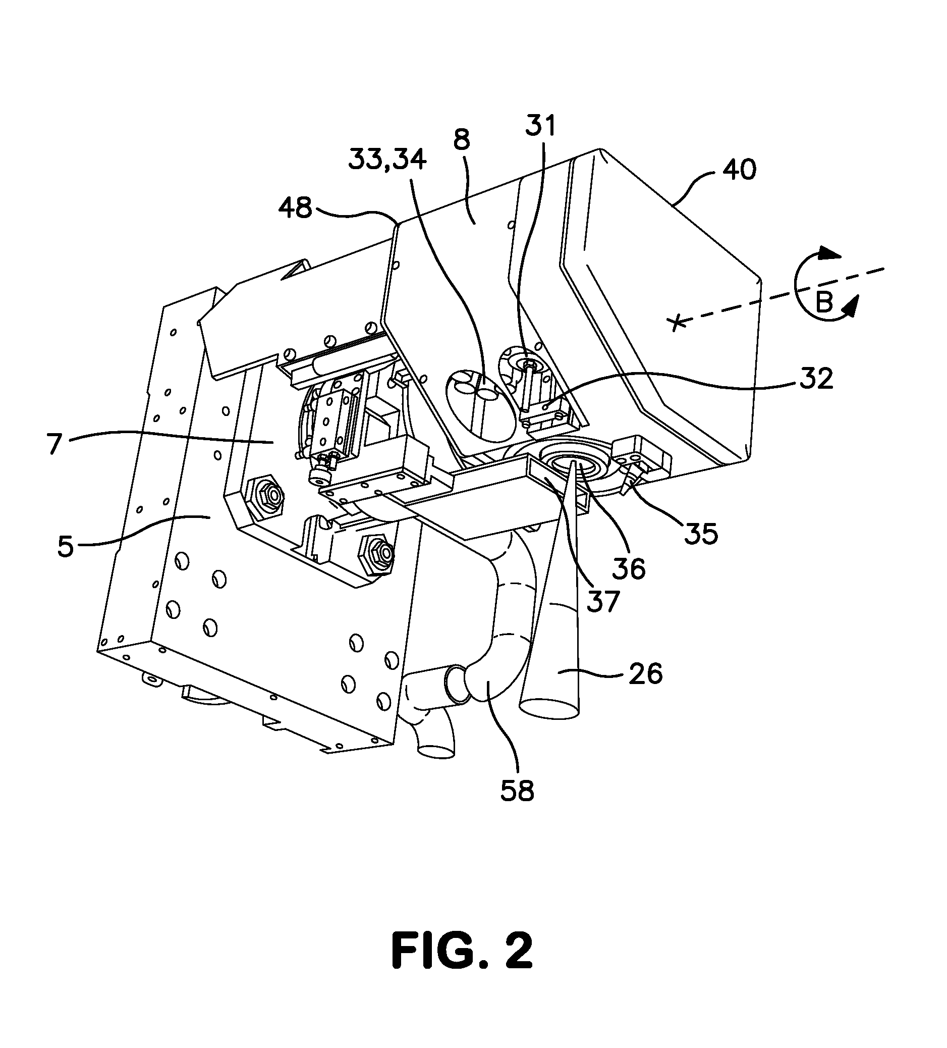
[0014]The machine tool shown schematically in FIG. 1 is mounted on a very stable frame made up of a broad horizontal base 1 to which a vertical pillar 2 is fixed. On the front face of the pillar 2, two vertical guide rails 3 and 4 guide the movement of a carriage 5 along the vertical axis Z of the machine, the movements of which are brought about the rotation of a screw 6 driven by a servomotor 16. The carriage 5 supports a horizontal barrel 15, the end of which is rigidly connected to a plate 7 for supporting the laser head 8, which is designed to pivot about a horizontal axis B corresponding to the axis of symmetry of the barrel 15 as shown in this figure. However, the horizontal barrel 15 may be omitted in the case of a different arrangement of the linear axes and also on certain machines of smaller size. In the second case, the plate 7 is directly joined to the carriage 5 (FIGS. 2 and 6-9) the pivoting laser head 8 constitutes the essential component of the machine. A high-power...


PUM

PropertyMeasurementUnit
diameteraaaaaaaaaa
volumeaaaaaaaaaa
energyaaaaaaaaaa

Abstract

A machine for machining workpieces by a laser beam. The optical fibre terminates at an optical output head (27) that defines the optical axis of the laser light beam, which vaporizes the material. The optical output head (27) is rigidly attached to the frame (49) or to the casing of the laser head so that said optical output head remains integrally fastened to said frame or casing during the rotation of the laser head about the horizontal pivot axis (B). The polluted gases generated in the machining area by the evaporation of material are collected by a suction nozzle (37) which is driven with the laser machining head during its rotation about the horizontal axis (B). A stream of clean dry gas is injected into the machining area by an injection nozzle (35) which is also driven with the laser machining head (8) during its rotation about the horizontal axis (B).

Description

BACKGROUND OF THE INVENTION[0001]The present invention relates to a machine for machining workpieces by means of a laser beam. The process, consisting in evaporating material from the surface of a workpiece by means of a focused laser beam, is now very widely used. In this type of machining, the laser beam is reflected by two steering mirrors, which can pivot very rapidly about two perpendicular axes, the rotation of said steering mirrors being controlled by a computer according to a raster lying in a plane. The method is widely used for engraving patterns on plane surfaces. The high-power laser beam is produced by a laser source, at the outlet of which the beam is conducted right to the surface to be treated by means of optical fibres and a series of static or rotary mirrors and other optical components. Most industrial applications are in the field of tooling and the manufacture of moulds in which it is necessary to engrave the surface of certain workpieces with very fine control ...

Claims


Application Information

Patent Timeline
Patent Type & Authority Applications(United States)
IPC IPC(8): B23K26/38
CPCB23K26/0823B23K26/0853B23K26/0869B23K26/147B23K37/047B23K26/365B23K37/0235B23K37/0452B23K26/16B23K26/361
Inventor PAGANELLI, DINO CATALDO
Owner CHARMILLES TECH SA
Why Eureka
Try Eureka