Laser beam machining apparatus

a laser beam and machining technology, applied in the direction of laser beam welding apparatus, lasers, manufacturing tools, etc., can solve the problems of laser oscillator, laser beam anomalous output, laser beam machining ability deterioration,

Inactive Publication Date: 2005-03-24
MITSUBISHI ELECTRIC CORP
View PDF3 Cites 34 Cited by
  • Summary
  • Abstract
  • Description
  • Claims
  • Application Information

AI Technical Summary

Problems solved by technology

Another cause that the air might enter the optical duct is machining gas to be supplied into the optical duct, and this is caused by using air sucked from a compressor into the optical duct as the machining gas.
The impure gas causes power distribution of the laser beam and increase in attenuation of the laser beam, and as a result, characteristics of the laser beam are deteriorated, and thus machining ability of the laser beam machining apparatus is deteriorated.
When anomalous output of the laser beam occurs, a defect in the laser oscillator is firstly regarded as a cause of the faul

Method used


Image

  • Laser beam machining apparatus
  • Laser beam machining apparatus
  • Laser beam machining apparatus

Examples


first embodiment

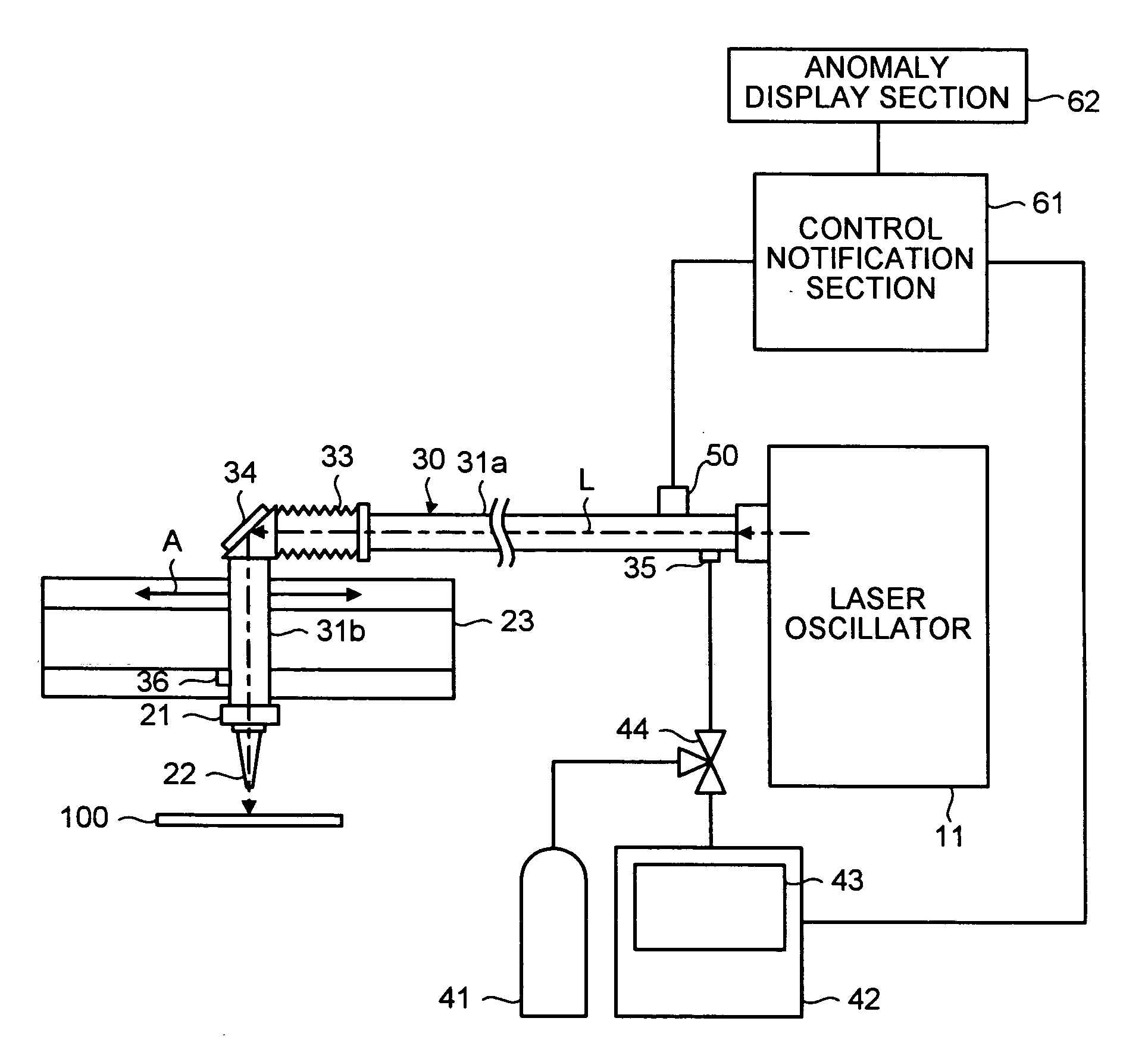
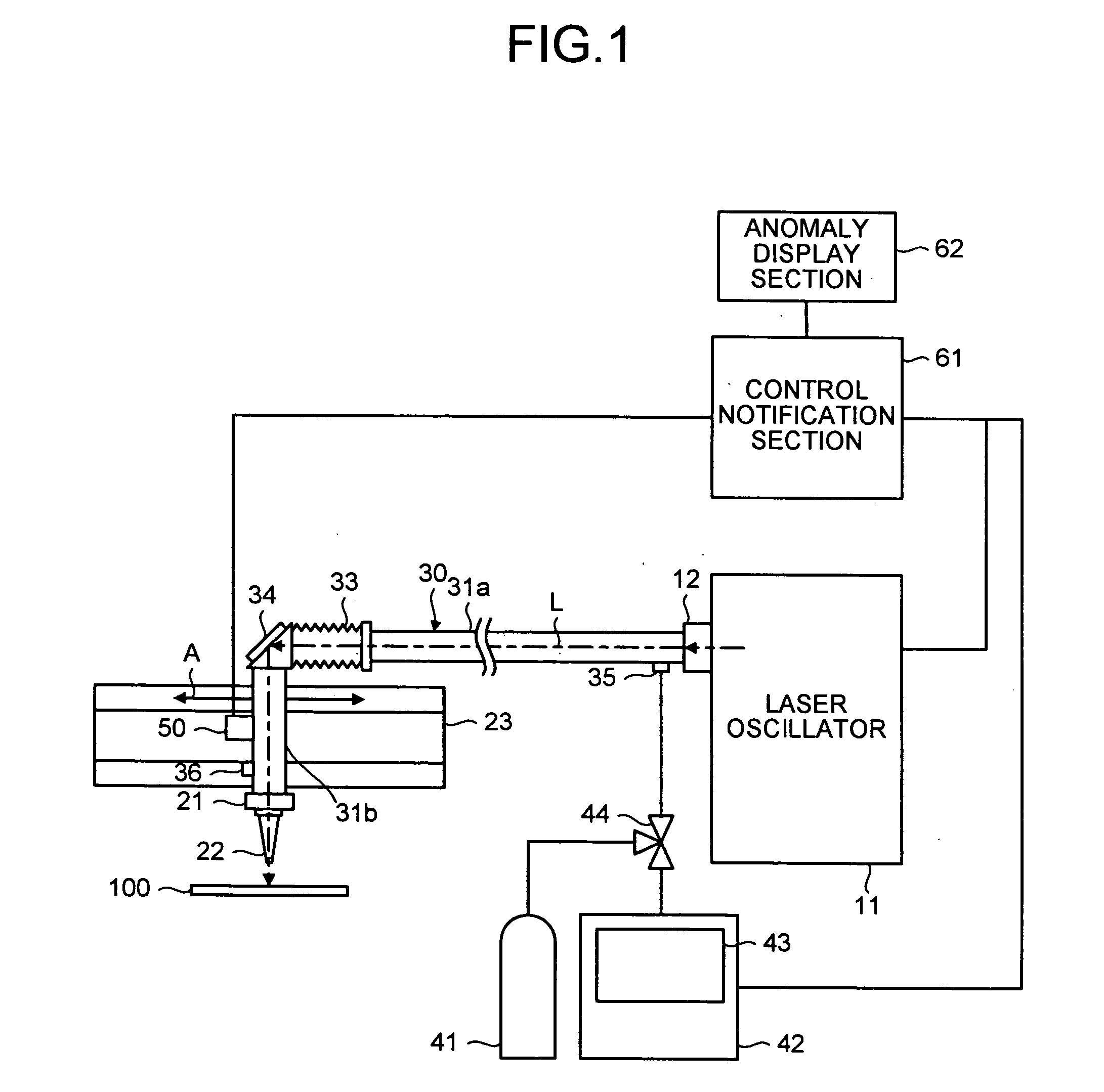
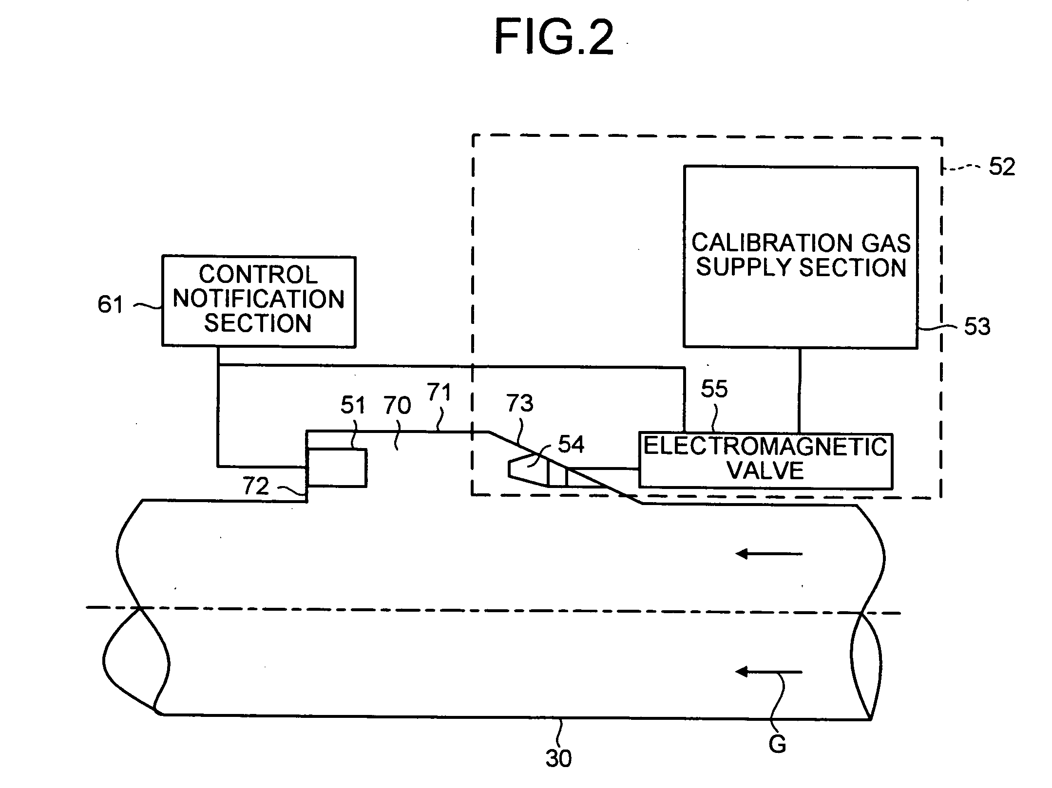
[0030] A first embodiment of the present invention is explained with reference to FIGS. 1 to 4. FIG. 1 is a schematic diagram of the laser beam machining apparatus according to the first embodiment of the present invention. FIG. 2 illustrates how a gas detector is attached to an optical duct. FIG. 3 is a flowchart of a process to detect anomaly in the laser beam machining apparatus according to the first embodiment. FIG. 4 is a flowchart of a process of calibration executed using the gas detector.

[0031] The laser beam machining apparatus includes a laser oscillator 11, such as a carbon dioxide gas laser oscillator (oscillation wavelength: 10.6 micro millimeters) which oscillates a laser beam, a machining head 21 which emits a laser beam output from the laser oscillator 11 to a workpiece (subject to be machined) 100 to be machined, and an optical duct 30 which guides the laser beam emerged from the laser oscillator 11 to the machining head 21 while an optical axis of the laser beam ...

second embodiment

[0050]FIG. 5 is a schematic diagram of a laser beam machining apparatus according to a second embodiment of the present invention. FIG. 6 is a flowchart of a process to detect an anomaly in the laser beam machining apparatus. Components which have same or similar configuration or same or similar functions as those in FIG. 1 are designated by the same reference numbers, and the explanation thereof is omitted.

[0051] As shown in FIG. 5, in the laser beam machining apparatus of the second embodiment, the gas detector 50 is positioned near the purge gas supply port 35. Although not shown, the gas detector may be provided in plurality. The other parts of configuration are the same as those in FIG. 1. It is preferable that the gas detector 50 is positioned opposite to the purge gas supply port 35 or slightly down stream side. The gas detector 50 is provided on the concave portion 70 on the optical duct 30 as shown in FIG. 2 of the first embodiment. The gas detector 50 is provided near the...

third embodiment

[0058]FIG. 7 is a schematic diagram of a laser beam machining apparatus according to a third embodiment of the present invention. FIG. 8 is to explain how the odor sensor detects anomalous portions. FIG. 9 is a flowchart of a process to detect an anomaly in the laser beam machining apparatus according to the third embodiment. Components which have same or similar configuration or same or similar functions as those in FIG. 1 are designated by the same reference numbers, and the explanation thereof is omitted.

[0059] As shown in FIG. 7, in the laser beam machining apparatus of the third embodiment, a first gas detector 50a is provided near the purge gas exhaust port 36, and a second gas detector 50b is provided near the purge gas supply port 35. Although not shown, the first and second gas detectors may be provided in plurality. The other parts of the configuration are the same as those in FIG. 1. A position where the second gas detector 50b is provided is desirably a portion in the o...


PUM


Abstract

A laser beam machining apparatus includes a laser oscillator, a machining head which that machines a workpiece using the laser beam. An optical duct has an optical system to guide the laser beam form the laser oscillator to the machining head. Purge gas is supplied into the optical duct from a purge gas supply port, and the purge gas is output from a purge gas exhaust port. A detector detects presence of undesired gas in the optical duct.

Description

TECHNICAL FIELD [0001] The present invention relates to a laser beam machining apparatus which carries out welding and cutting and is capable of detecting mixing of impure gas in purge gas filling a light guide duct guiding a laser beam. BACKGROUND ART [0002] Various types of laser machining apparatuses are known. For example, Japanese Patent Application Laid-Open Publication No. 5-8079 (see page 2, FIGS. 1 and 2) discloses a conventional laser beam machining apparatus that transmits a laser beam stably for long time and can weld and cut a subject to be machined with high accuracy. This laser beam machining apparatus includes a laser oscillator, a laser robot, an optical duct, and a machining gas supply unit. The laser oscillator has a beam transmission line including a laser outgoing port of an airtight mechanism. The laser robot has an articulated configuration which can emit a laser beam to an arbitrary position of the subject to be machined. The optical duct guides the laser bea...

Claims


Application Information

Patent Timeline
IPC IPC(8): B23K26/03B23K26/064B23K26/00B23K26/14H01S3/00H01S3/02
CPCB23K26/03B23K26/123B23K26/422B23K26/1476B23K26/1441B23K26/702B23K26/1436H01S3/10H01S3/0953
Inventor ARAKAWA, YOSHIFUMIYOKOI, SHIGERU
Owner MITSUBISHI ELECTRIC CORP
Why Eureka
Try Eureka