Position-of-magnetic-pole detecting device
- Summary
- Abstract
- Description
- Claims
- Application Information
AI Technical Summary
Benefits of technology
Problems solved by technology
Method used
Image
Examples
Embodiment Construction
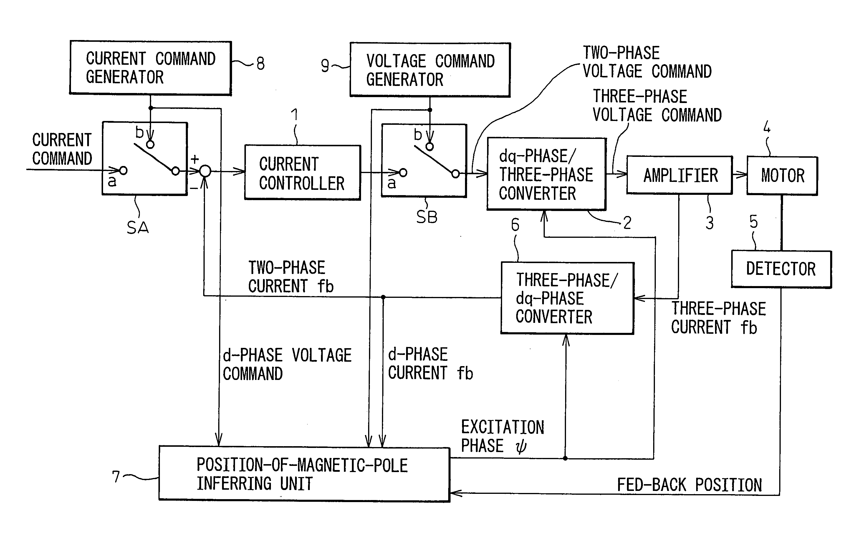
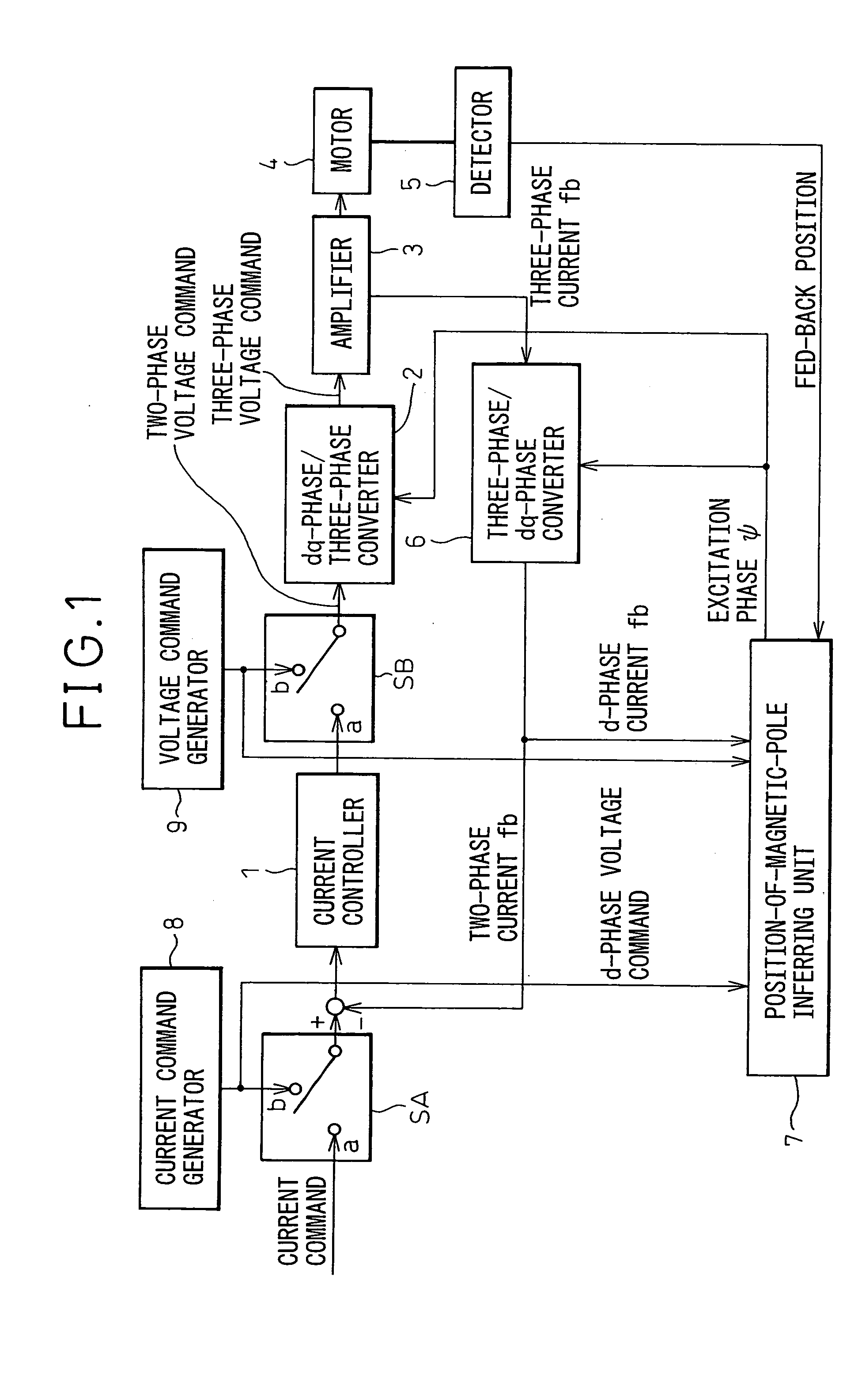
[0023]FIG. 1 is a block diagram of an embodiment of motor control equipment based on which a position-of-magnetic-pole detecting device in accordance with the present invention is realized. For normal driving and control of a motor, switches SA and SB have the contacts a thereof made. A converter 6 for converting a three-phase current into a dq-phase current converts a three-phase fed-back current into a dq-phase fed-back current. The d-phase and q-phase current components of the dq-phase fed-back current are subtracted from d-phase and q-phase current commands respectively, whereby deviations of the d-phase and q-phase current components are calculated. A current controller 1 performs feedback control on a current and issues a voltage command. Based on the position of a rotor included in the motor which is detected by a detector 5, a position-of-magnetic-pole inferring unit 7 calculates an excitation phase ψ. Based on the excitation phase, a converter 2 for converting a dq-phase vo...
PUM
 Abstract
Description
Claims
Application Information
 - R&D
- Intellectual Property
- Life Sciences
- Materials
- Tech Scout
- Unparalleled Data Quality
- Higher Quality Content
- 60% Fewer Hallucinations
Browse by: Latest US Patents, China's latest patents, Technical Efficacy Thesaurus, Application Domain, Technology Topic, Popular Technical Reports.
© 2025 PatSnap. All rights reserved.Legal|Privacy policy|Modern Slavery Act Transparency Statement|Sitemap|About US| Contact US: help@patsnap.com


