Shape measurement device and shape measurement method

Inactive Publication Date: 2012-09-13
SHARP KK
View PDF2 Cites 1 Cited by
  • Summary
  • Abstract
  • Description
  • Claims
  • Application Information

AI Technical Summary

Benefits of technology

[0017]With the above feature, the shape measurement device of the present invention causes the measurement object detecting means to detect that a measurement object is located at the position of the velocity measuring means from which position the velocity measuring means emits a laser beam, and thus accurately detects the position of a measurement object and allows the measurement object velocity extracting means to calculate only the velocity of the measurement object inside the arithmetic processing means. The shape measurement device thus (i) calculates a velocity mean value from at least a part of data of the velocity of the measurement object, (ii) removes, from the data of the velocity of the measurement object, a component attributed to the velocity mean value, and then (iii) calculates a time integral of the velocity to calculate displacement. This arrangement prevents influence of, for example, a tilt in the measurement object and an offset value for the velocity measuring means, and consequently improves accuracy of measurement.
[0019]The above feature prevents influence of, for example, a tilt in the measurement object and an offset value for the velocity measuring means, and allows even the amount of displacement to be calculated immediately when velocity data is obtained. This makes it possible to obtain data of a highly accurate measurement in real time.
[0021]With the above feature, the shape measurement method (i) calculates a velocity mean value from data of the velocity of a measurement object, (ii) removes, from the data of the velocity of the measurement object, a component attributed to the velocity mean value, and then (iii) integrates the velocity. This makes it possible to prevent influence of, for example, a tilt in the measurement object and an offset value for the velocity measuring step, and consequently improves accuracy of measurement.
[0023]With the above feature, the arithmetic processing means calculates acceleration of a measurement object by differentiating velocity data obtained by a measurement object velocity extraction for extracting the velocity of a measurement object, and integrates the acceleration twice. This makes it possible to prevent influence of, for example, a tilt in the measurement object and an offset value for the velocity measuring step. The above feature further allows the amount of displacement to be calculated immediately when velocity data is obtained, and consequently makes it possible to obtain data of a highly accurate measurement in real time.Advantageous Effects of Invention
[0025]Another shape measurement device of the present invention (i) calculates a velocity mean value from data of the velocity of a measurement object, (ii) removes, from the data of the velocity of the measurement object, a component attributed to the velocity mean value, and then (iii) integrates the velocity. This makes it possible to advantageously prevent influence of, for example, a tilt in the measurement object and an offset value for a velocity measurement, and consequently improves accuracy of measurement.

Problems solved by technology

However, if a trigonometrical survey involving a laser displacement meter were to be carried out inside a film formation device such as the MOCVD device 100 illustrated in FIG. 10, radiation due to the substrate temperature would make it difficult to separate laser light from radiant light.
It has thus been impossible to carry out a trigonometrical survey in a MOCVD device 100.
The method involving a laser Doppler velocimeter is, however, disadvantageous in that its laser output and a laser light receiving section, for example, are changed by such factors as an operating environment and time elapse.
Velocity integration of an offset value other than 0 as above erroneously adds the offset value to a measurement result, which may make it impossible to measure a warp in a substrate.
However, in the case where the measurement object is extremely low in, for example, moving velocity and operating frequency, setting a high pass filter unfortunately removes even a velocity to be measured.
While the MOCVD device 100 causes substrates 3 to revolve in order to prevent temperature variation, this revolution is normally low in velocity, and further, a warp change (warp amount) in a substrate ranges from several μm to several tens of μm., which has made it difficult to set a high pass filter.
Inside a MOCVD device, however, a substrate has displacement that increases with time due to film deposition, that is, with an increase in the number of rotations.
The above method thus does not yield 0 for the integrated value of true displacement for the case in which a substrate is rotated once.
Thus, even if the method of Patent Literature 2 is used to measure a warp in a substrate inside a MOCVD device, it may be impossible to separate out only a velocity change caused by an actual warp in a substrate, thus raising the risk of a decrease in accuracy.
Further, if the amount of displacement due to, for example, a tilt and vibration of the mobile platform is larger than that of displacement caused by a warp in a substrate, that is, a measurement object, measurements have been made of such a tilt of the mobile platform instead, thus making it impossible to measure a warp in a substrate.

Method used


Image

  • Shape measurement device and shape measurement method
  • Shape measurement device and shape measurement method
  • Shape measurement device and shape measurement method

Examples


embodiment 1

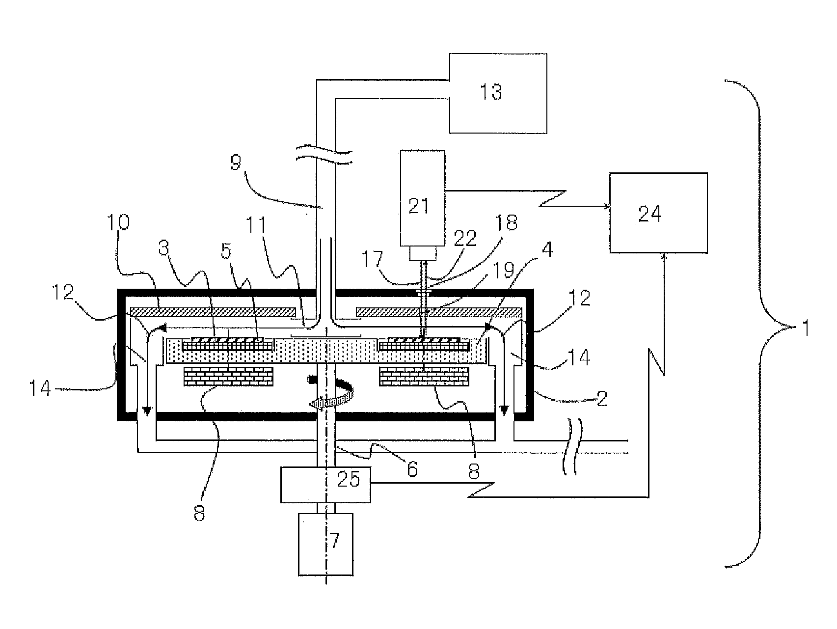
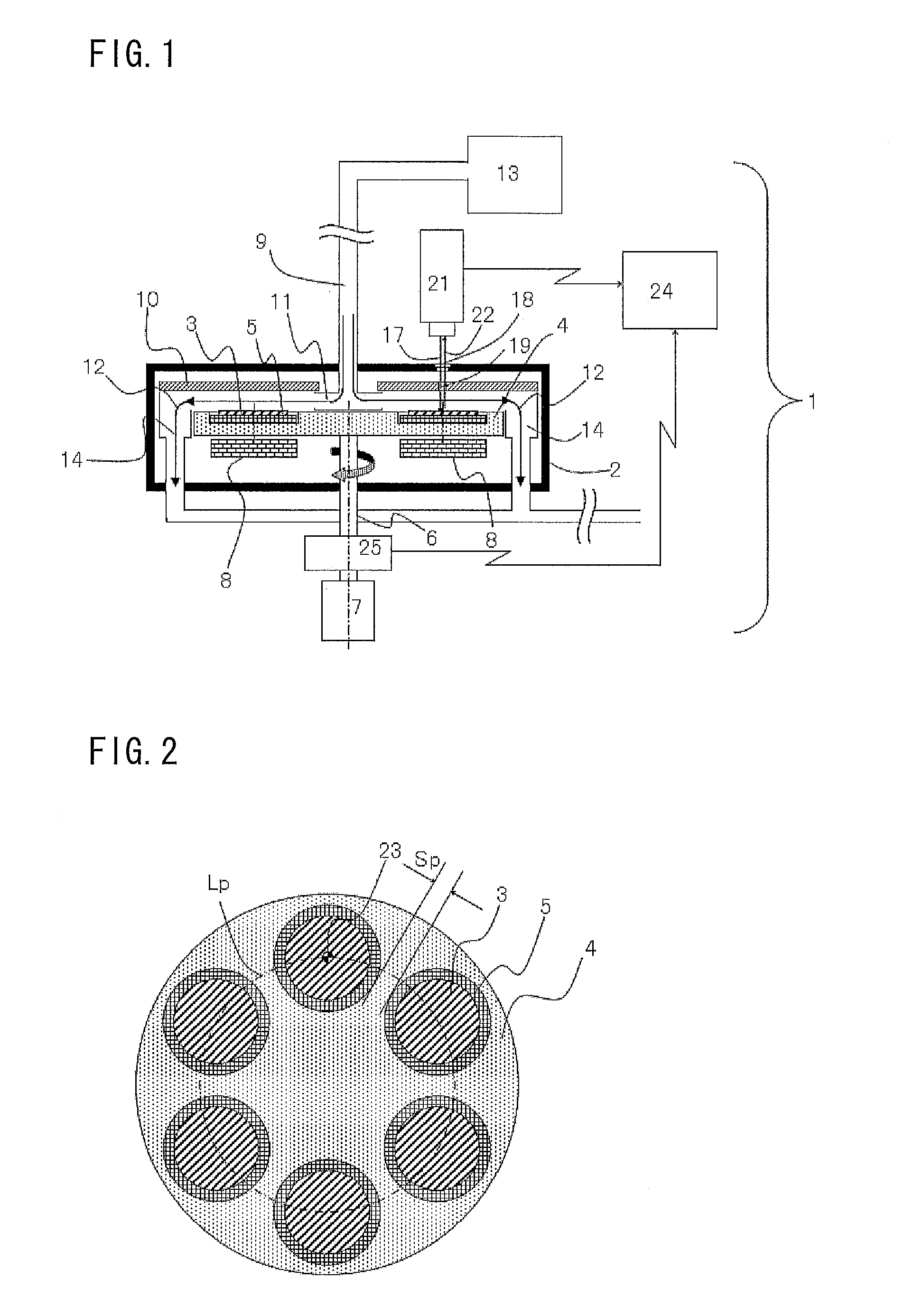
[0040]With reference to FIGS. 1 and 2, the description below deals with, as a shape measurement device of the present invention, Embodiment 1, in which the present invention is applied to a MOCVD device including (i) measurement object detecting means in which a rotation angle measuring instrument is incorporated and (ii) velocity measuring means which makes use of the principle of the Doppler effect of a laser beam. FIG. 1 is a conceptual diagram illustrating a configuration of a MOCVD device (shape measurement device) 1 of Embodiment 1. FIG. 2 is a plan view illustrating a relation between placement plates 5 (holders) of the MOCVD device 1 and substrates 3 (measurement objects).

[0041]The MOCVD device 1, as illustrated in FIG. 1, includes a cylindrical reaction chamber 2, which contains a rotating table 4. The rotating table 4 is provided with, on an upper portion thereof, a plurality of placement plates 5 that are each located at a particular radial position and that are separated...

embodiment 2

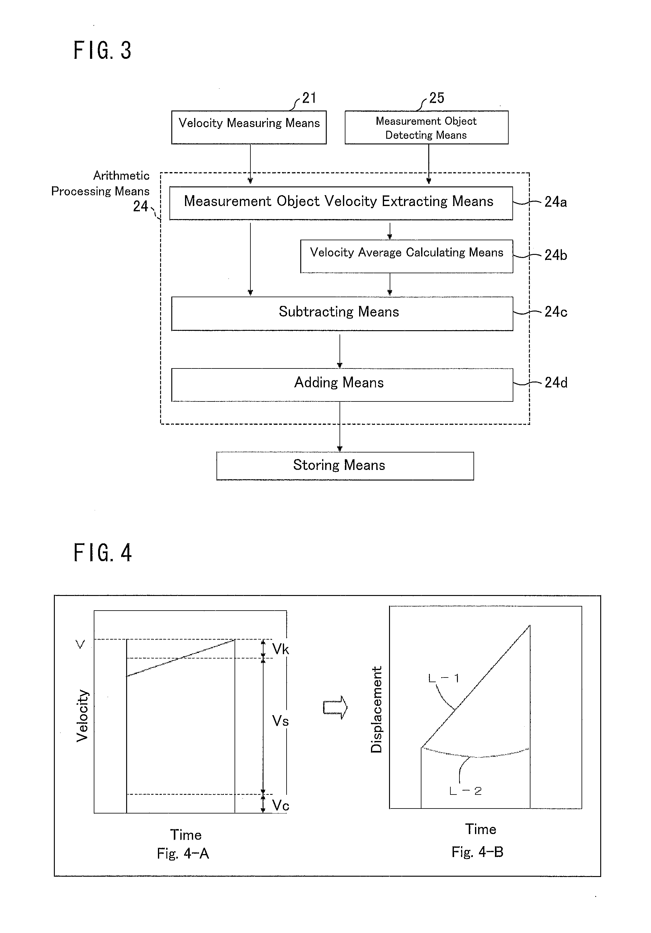
[0055]The following description deals with Embodiment 2 with reference to FIG. 5. FIG. 5 is a diagram illustrating the flow of a data processing by a MOCVD device (shape measurement device) of Embodiment 2, that is, a diagram illustrating a processing carried out inside an arithmetic processing means 24A. The arithmetic processing means 24A of the Embodiment 2 includes: measurement object velocity extracting means 24a; differential computing means 24e; adding means (velocity calculation) 24f; and adding means (displacement calculation) 24g.

[0056]As in Embodiment 1, the velocity measuring means 21 and the measurement object detecting means 25 supply respective output values to the arithmetic processing means 24A. The measurement object velocity extracting means 24a included in the arithmetic processing means 24A extracts the respective velocities of the substrates 3 from the respective output values of the velocity measuring means 21 and the measurement object detecting means 25. Th...

embodiment 3

[0059]The following description deals with Embodiment 3 with reference to FIG. 7 through 9. FIG. 7 is a diagram illustrating the flow of a data processing by a MOCVD device (shape measurement device) of Embodiment 3.

[0060]The MOCVD device of the present embodiment includes: arithmetic processing means 24 or 24A described in Embodiment 1 or 2; and second arithmetic processing means 26. The second arithmetic processing means 26 includes: smoothing processing means 26a; coordinate extracting means 26b; linear formula converting means 26c; displacement calculating means 26d; and warp calculating means 26e.

[0061]The MOCVD device of the present embodiment obtains displacement values with use of the arithmetic processing means 24 or 24A similar to that of Embodiment 1 or 2, and temporarily supplies the displacement values to storing means. The smoothing processing means 26a included in the second arithmetic processing means 26, on the basis of a relation between (i) displacement values te...


PUM


Abstract

A MOCVD device (shape measurement device) of the present invention measure including the shape of measurement object with use of a mobile platform (rotating table) for moving a substrate, that is, the measurement object, velocity measuring means (21) utilizing the Doppler effect of a laser beam, measurement object detecting means (25), arithmetic processing means (24), and storing means. The arithmetic processing means (24) includes: measurement object velocity extracting means (24a) for extracting the velocity of a measurement object; velocity average calculating means (24b) for calculating a velocity mean value from velocity data; subtracting means (24e) for subtracting the velocity mean value from the velocity data; and adding means (24d) for integrating the velocity.

Description

TECHNICAL FIELD[0001]The present invention relates to a device, such as a MOCVD device, and a method both for measuring the shape of a measurement object such as a substrate in a state in which the measurement object is placed on a mobile platform that is rotated or planetarily rotated.BACKGROUND ART[0002]Crystal growth for a compound semiconductor such as a semiconductor laser element and an LED (light-emitting diode) element typically involves use of a MOCVD (metal organic chemical vapor deposition) device. A MOCVD device, which is high in productivity and easy to maintain, is suitable for industrial mass production of such elements.[0003]FIG. 10 illustrates an example MOCVD device. The MOCVD device 100 includes a reaction chamber 2, in which a plurality (six in this example) of substrates 3 are placed on respective placement plates 5 provided to an upper surface of a rotating table 4.[0004]FIG. 11 is a plan view illustrating a relation between a holder of the MOCVD device 100 and...

Claims


Application Information

Patent Timeline
IPC IPC(8): G01B17/06G06F15/00
CPCG01B11/24G01S11/10G01R31/309H05K13/08G01M5/0033
Inventor INOSHIRI, RYOU
Owner SHARP KK
Why Eureka
Try Eureka