
Method and circuit arrangement for synchronizing plural oscillators

a technology of plural oscillators and circuits, applied in the direction of automatic control of pulses, discontinuous tuning with variable tuning elements, radio transmission, etc., can solve the problems of complete or perfect synchronization of oscillators, interference with receiver noise, multi-path interference, etc., to achieve simple or uncomplicated filter tuning or balancing, simple and economical circuit technology

Inactive Publication Date: 2005-05-19
ATMEL GERMANY
View PDF2 Cites 18 Cited by
  • Summary
  • Abstract
  • Description
  • Claims
  • Application Information

AI Technical Summary

Benefits of technology

[0010] In view of the above, it is an object of the present invention to provide a method and an apparatus for synchronizing plural oscillators, through the use of a simple and economical circuit technology and a simple or uncomplicated filter tuning or balancing. The invention further aims to avoid or overcome the disadvantages of the prior art, and to achieve additional advantages, as apparent from the present specification. The attainment of these objects is, however, not a required limitation of the claimed invention.

Problems solved by technology

Continuously varying or changing reception conditions are also the cause of so-called multi-path interferences.
In this context, it is problematic that the respective local oscillators of the various receivers must be very strongly decoupled from one another in order to avoid mutual influence therebetween.
However, phase noise of the oscillators as well as noise components of the phase locked loops prevent a complete or perfect synchronization of the oscillators when all of the oscillators are to operate on the same frequency.
Moreover, an incomplete decoupling of the oscillators relative to one another leads to a mutual or interactive influence therebetween, which is noticeable as interfering noise in the receiver.
This alternative, however, requires relatively complicated and expensive high frequency switches, in order to ensure an adequate or sufficiently high decoupling in the switched-off condition.
Since a tuning voltage from the phase locked loop of a local oscillator is used for adjusting or tuning subsequent or following filter circuits of the receiver, for this purpose the tuning voltage from the phase locked loop of the active local oscillator must also be delivered further on to the other receivers, which is complicated with respect to the necessary circuit arrangements therefor.
Moreover, the tuning adjustment or balancing of the individual receivers is complicated, since an adjustment or balancing of the filter circuits is based on the control voltage of the oscillator (e.g. voltage controlled oscillator VCO).
In this regard, the filter balancing is further made more difficult if the individual receivers are respectively subjected to different surrounding environmental temperatures, such that the several receivers will exhibit different temperature-dependent characteristic behaviors.

Method used


Image

  • Method and circuit arrangement for synchronizing plural oscillators
  • Method and circuit arrangement for synchronizing plural oscillators
  • Method and circuit arrangement for synchronizing plural oscillators

Examples


Embodiment Construction

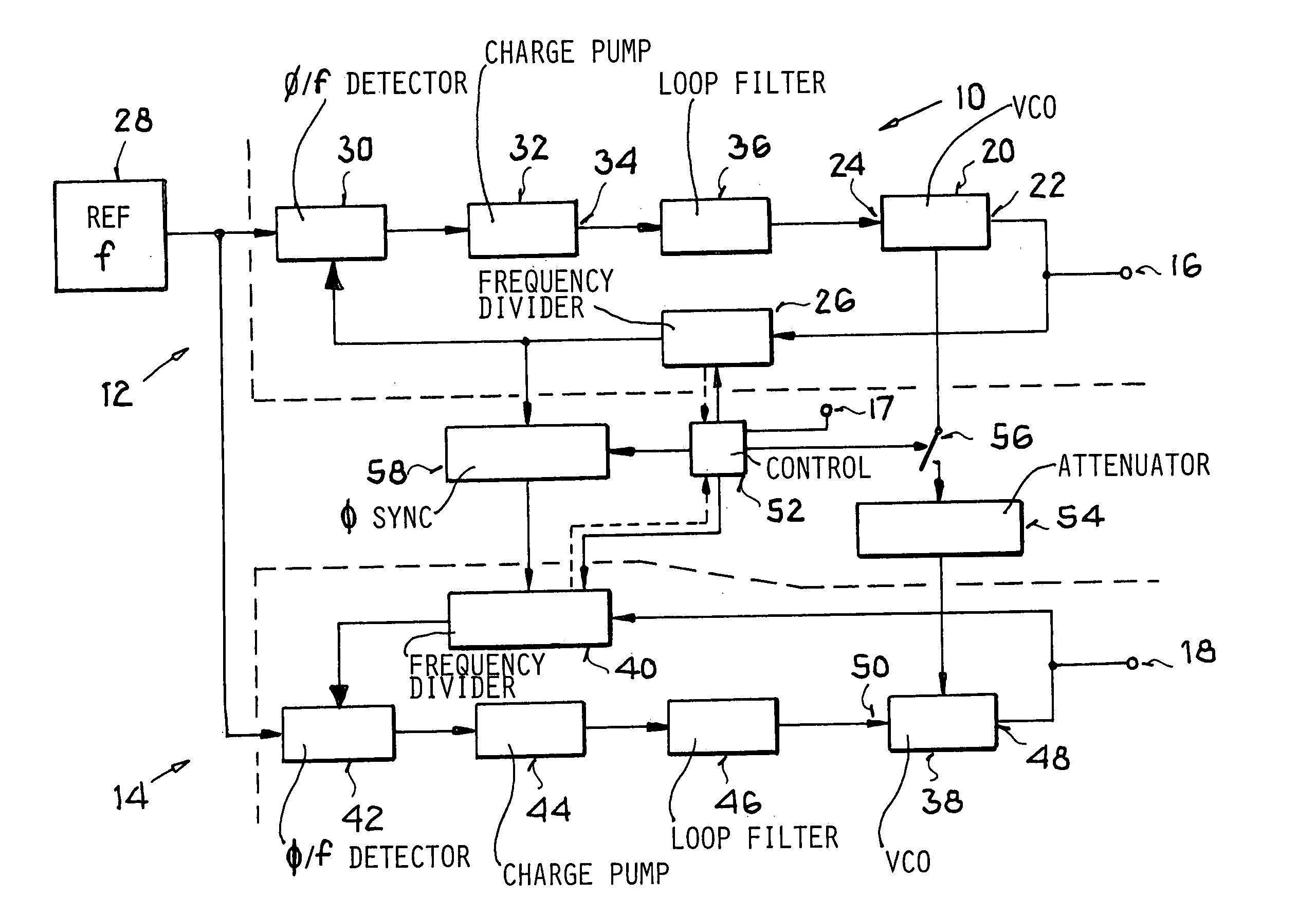
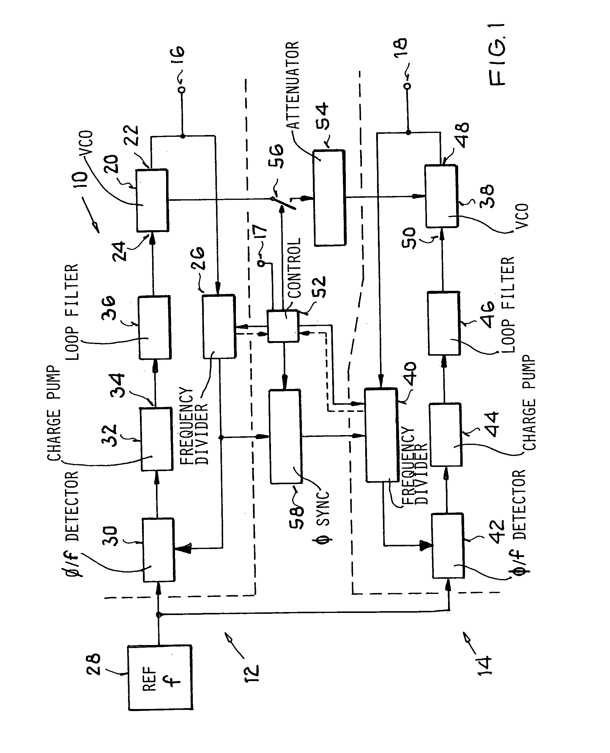
[0029]FIG. 1 schematically shows the overall construction of a circuit arrangement 10 according to the invention, having a first phase locked loop 12 that provides a first oscillator frequency at a first output 16 of the arrangement 10, and a second phase locked loop 14 that provides a second oscillator frequency at a second output 18 of the arrangement 10. The first phase locked loop 12 comprises a first oscillator 20, for example embodied as a voltage controlled oscillator (VCO) 20. At its output 22, the first oscillator 20 provides an alternating voltage signal having a frequency (i.e. the first oscillator frequency) that is dependent on the value of a control voltage that is provided to an input 24 of the first oscillator 20. The alternating voltage signal of the first oscillator 20 is provided to the first output 16, and is further provided to a first controllable frequency divider 26, by which the frequency of the alternating voltage signal is divided down to the level of a re...


PUM


Abstract

A circuit arrangement includes a first phase locked loop to generate a first oscillator frequency, a second phase locked loop to generate a second oscillator frequency, a reference frequency emitter connected to a reference frequency input of both phase locked loops, and a signal attenuator and optionally a switch connected between a master signal output of the first (master) loop and an input of the second (slave) loop. In a method, a common reference frequency is provided to both loops, the first loop generates a first oscillator frequency, and the second loop generates a second oscillator frequency that matches the first oscillator frequency in at least one operating mode and optionally differs from the first oscillator frequency in another operating mode. The frequency matching in one of the modes involves feeding an attenuated signal from the first loop operating as a master into the second loop operating as a slave.

Description

PRIORITY CLAIM [0001] This application is based on and claims the priority under 35 U.S.C. §119 of German Patent Application 103 54 521.2, filed on Nov. 14, 2003, the entire disclosure of which is incorporated herein by reference. FIELD OF THE INVENTION [0002] The invention relates to both a method and a circuit arrangement for generating a first oscillator frequency with a first phase locked loop and a second oscillator frequency with a second phase locked loop, wherein the second oscillator frequency may be matched to the first oscillator frequency. BACKGROUND INFORMATION [0003] Various methods and a circuit arrangements of the above mentioned general type are conventionally known. Such methods and circuit arrangements are utilized, for example, in the field of mobile reception of radio signals, such as in modern automobile radios, whereby various specific techniques are used, in order to ensure an uninterrupted and interference-free reception of the radio signals even under conti...

Claims


Application Information

Patent Timeline
Patent Type & Authority Applications(United States)
IPC IPC(8): H03J5/14H03L7/00H03L7/07H03L7/18H03L7/22H04B1/16
CPCH03L7/07H03L2207/06H03L7/18
Inventor REBEL, REIMUND
Owner ATMEL GERMANY
Learn More