Method of determining the gain characteristic of a distributed Raman amplifier

a raman amplifier and gain characteristic technology, applied in the field of optical fiber communication systems, can solve the problems of inability to accurately predict the performance of raman amplifiers, gain, gain equalization and noise spectrum, local losses, etc., and achieve the effect of accurate and simple method of determining

Inactive Publication Date: 2005-05-19
ALCATEL LUCENT SAS
View PDF1 Cites 43 Cited by
  • Summary
  • Abstract
  • Description
  • Claims
  • Application Information

AI Technical Summary

Benefits of technology

[0009] The invention thus provides a very accurate and simple method to determine the Raman gain characteristics in the field without requiring special signal sources and other dedicated measurement equipment.

Problems solved by technology

It is impossible to accurately predict the performance of a Raman amplifier, including gain, gain equalization and noise spectrum, without thorough knowledge of the fiber types, properties characteristics, and condition along the fiber optic transmission line.
In addition, local losses due to for example fiber splices cannot be predicted accurately and the installed fiber may not have exactly the same Raman efficiency as the fiber of that type that had been preliminary calibrated in the laboratory.
A measurement of the Raman on / off gain in the field is, however, difficult because it may on the one hand not be possible at system installation to dispose a signal source for the measurement and on the one hand, the two fiber ends where the measurement has to be performed are typically 50 to 100 km apart.

Method used


Image

  • Method of determining the gain characteristic of a distributed Raman amplifier
  • Method of determining the gain characteristic of a distributed Raman amplifier
  • Method of determining the gain characteristic of a distributed Raman amplifier

Examples


Embodiment Construction

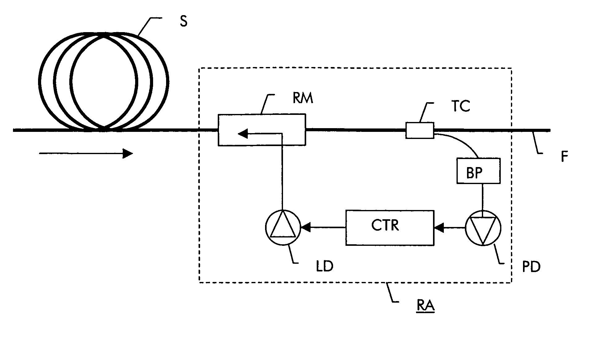
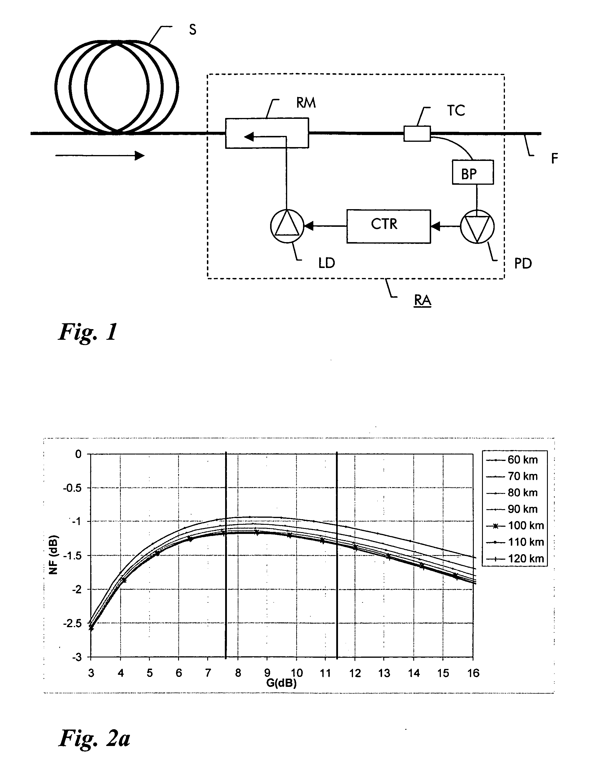
[0013] A Roman amplifier which is to be characterized by the measurement according to the invention is shown in FIG. 1. The Raman amplifier RA uses as gain medium a preceding fiber link F, the Raman gain characteristics of which need to be determined. The Raman amplifier RA as such contains a pump source LD and a Raman multiplexer RM which couples the pump light from the pump source LD in backwards direction into the fiber link F. The pump light causes stimulated Raman scattering in the fiber span length S when a signal traverses the link and thus amplifies the signal. A tap coupler TC is provided at the output of the Raman amplifier which serves to extract a small fraction of the amplified signal light from the fiber and feed it via a band-pass filter BP to a photodiode PD which determines an output power value of the signal.

[0014] In operation, the pump light power must be adjusted to the required Roman gain. Such adjustment, however, requires thorough knowledge of a parameter ch...


PUM


Abstract

A method of determining the gain characteristic of a Raman amplifier includes the steps of launching a pump light signal into a fiber; preliminary adjusting the power of the pump light signal to a value that lies in a range where the amplified spontaneous emission noise originating from the pump light signal is substantially proportional to the on/off gain provided by the power of the pump light signal; monitoring the power of the amplified spontaneous emission noise signal; varying the power of the pump light signal; measuring a variation in the power of the amplified spontaneous emission noise signal corresponding to the pump power variation; and determining the gain characteristic of the amplifier from the relative variation in pump power and the measured variation in noise power.

Description

TECHNICAL FIELD [0001] The invention relates to the field of optical fiber communication systems and more particularly to a method and apparatus for determining gain characteristic of a distributed Raman amplifier. The invention is based on a priority application EP 03 292 825.1 which is hereby incorporated by reference. BACKGROUND OF THE INVENTION [0002] In optical fiber communication systems, optical signals propagating along an optical fiber undergo signal attenuation due to absorption and scattering in optical fibers. Therefore, optical signals require periodic amplification over long distances, which can be performed either by electrical repeaters or by optical amplifiers. Known optical amplifier types include Erbium-doped fiber amplifiers (EDFAs), semiconductor optical amplifiers and Raman amplifiers. Due to its flat gain over a wide signal wavelength band, the Raman amplifier has gained increasing attention in the recent past as ideal amplifier candidate for wavelength divisi...

Claims


Application Information

Patent Timeline
Patent Type & Authority Applications(United States)
IPC IPC(8): G01M11/00H04B10/073H04B10/291
CPCG01M11/319H04B10/2916H04B10/0731
Inventor MARTINELLI, CATHERINECHARLET, GABRIEL
Owner ALCATEL LUCENT SAS
Why Eureka
Try Eureka