
Microscope system

a microscope and system technology, applied in the field of microscope systems, can solve problems such as user a great deal of troubl

Inactive Publication Date: 2005-05-19
NIKON CORP
View PDF3 Cites 27 Cited by
  • Summary
  • Abstract
  • Description
  • Claims
  • Application Information

AI Technical Summary

Benefits of technology

[0008] A microscope system according to a first aspect of the present invention comprises an objective optical system that uses an objective among a plurality of objectives with different magnifications to observe a specimen; a focus adjustment device that adjusts a focus position of the objective optical system; a start instruction device that instructs to start operation of the focus adjustment device; an objective selection device that selects the objective among the plurality of objectives; a switching instruction device that instructs the objective selection device to change the objective; and a control device that controls the operation of the focus adjustment device in accordance with an instruction to change the objective issued from the switching instruction device when no instruction to start the operation of the focus adjustment device is issued from the start instruction device.
[0009] A microscope system according to a second aspect of the present invention comprises a macro image capturing device that captures a macro image of a specimen; a macro image display device that displays the macro image captured by the macro image capturing device; a specifying device that specifies an observation position of a micro image in the specimen on a display screen of the macro image displayed in the macro image display device; an observation position control device that matches the observation position of the specimen specified by the specifying device with an optical axis of an objective optical system; a micro image capturing device that captures the micro image of the specimen at the observation position specified by the specifying device via the objective optical system; a micro image display device that displays the micro image captured by the micro image capturing device; a focus adjustment device that adjusts a focus position of the objective optical system; and a control device that (a) controls the micro image capturing device to captures the micro image of the specimen, (b) controls the focus adjustment device to carry out focus adjustment operation after the captured micro image is displayed on the micro image display device, (c) controls the micro image capturing device to capture the micro image again, and (d) updates the micro image displayed on the micro image display device.
[0010] A microscope system according to a third aspect of the present invention comprises an objective optical system used to observe a specimen; a focus adjustment device that adjusts a focus position of the objective optical system; a start instruction device that instructs to start operation of the focus adjustment device; a specifying device that specifies an observation position of the specimen; an observation position control device that matches the observation position of the specimen specified by the specifying device with an optical axis of the objective optical system; and a control device that engages the focus adjustment device in operation after the observation position control device matches the observation position with the optical axis in accordance with a signal from the specifying device in a case no instruction to start the operation is issued from the start instruction device.

Problems solved by technology

However, in the above-described microscope system of the related art, it is necessary for a user to instruct to start the focusing operation in order to engage the focusing device in operation again after the magnification of the objective is changed or after the observation point is changed during observation of the specimen, causing the user a great deal of trouble.

Method used


Image

  • Microscope system
  • Microscope system
  • Microscope system

Examples


first embodiment

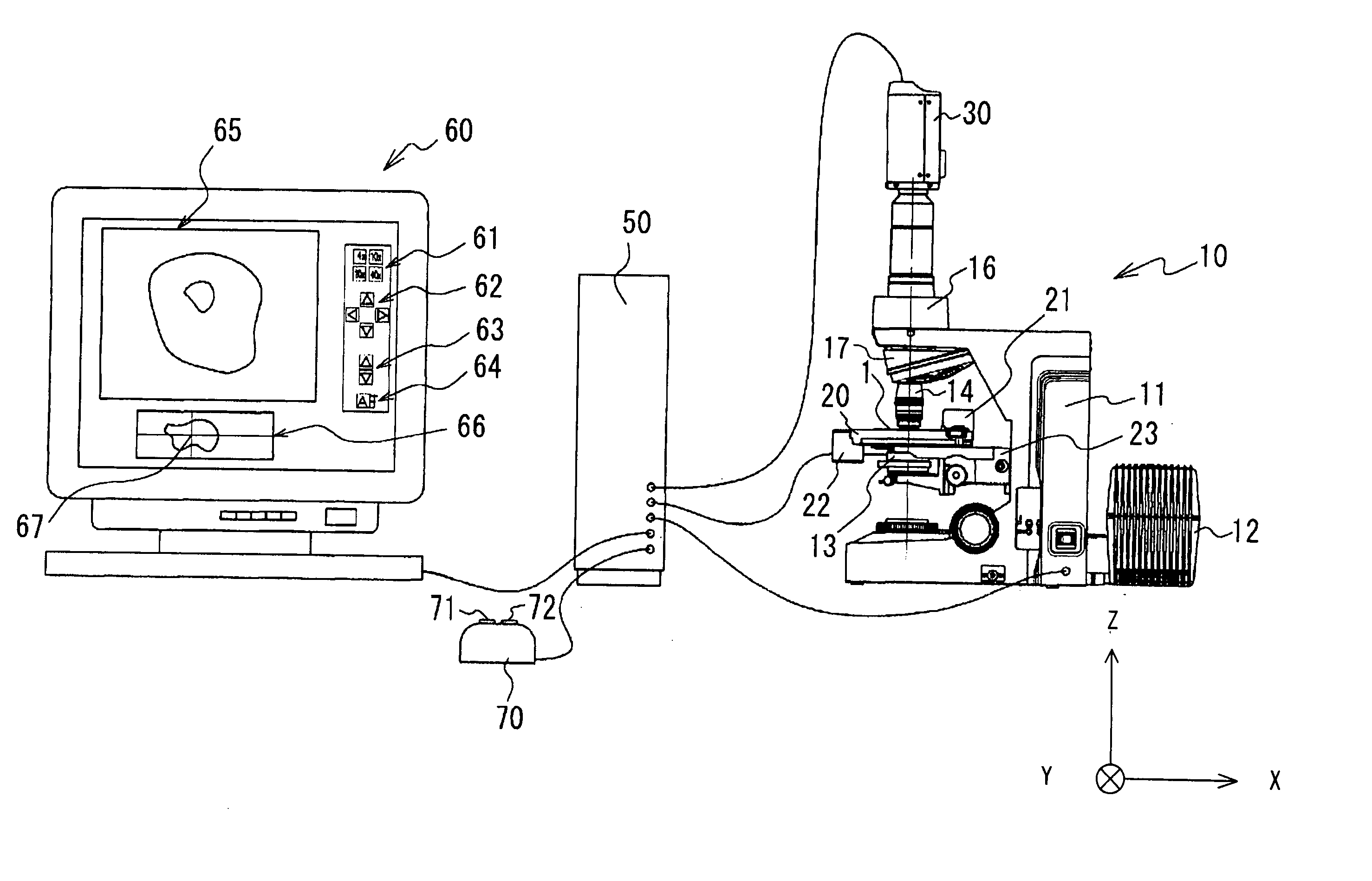
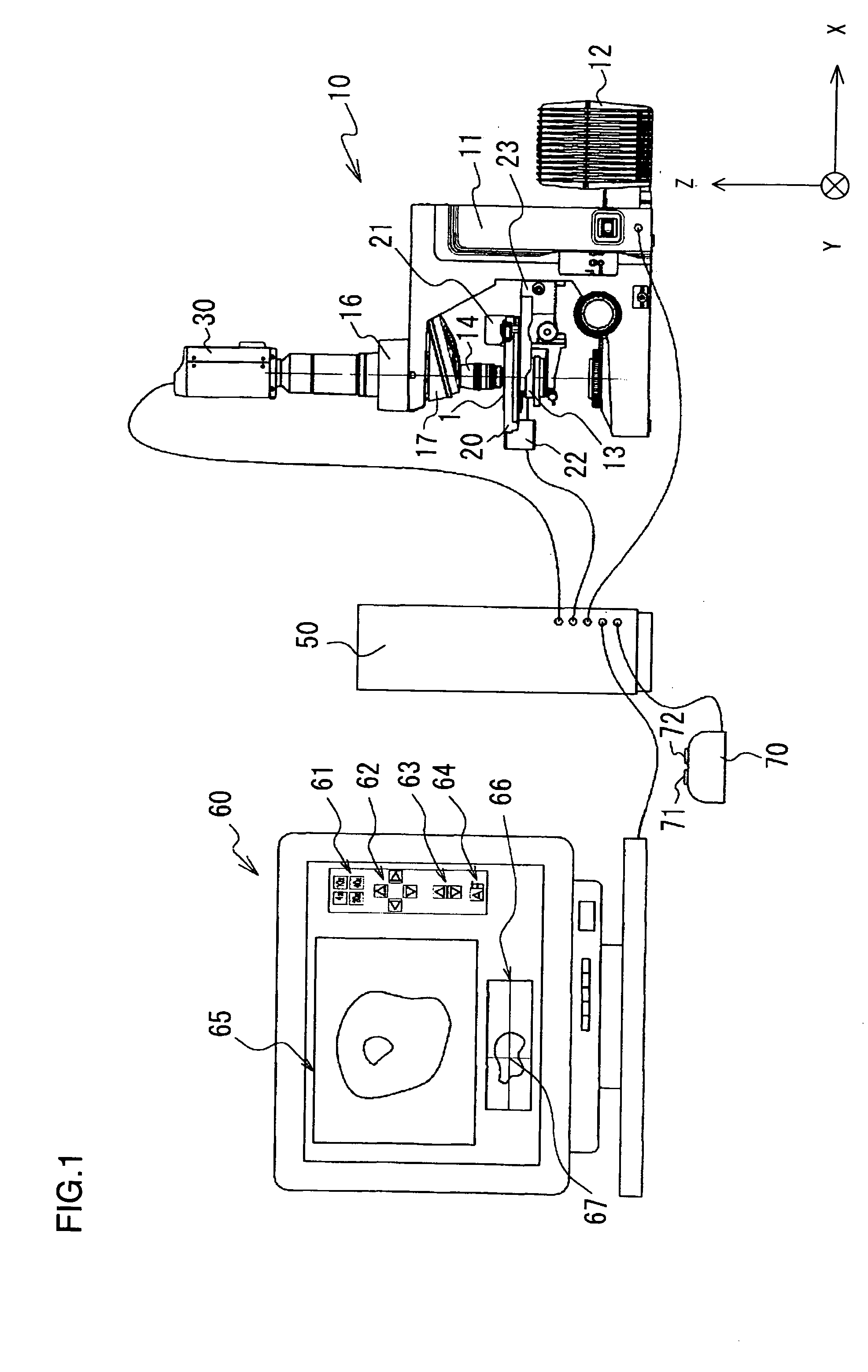
[0016]FIG. 1 shows an overall structure adopted in a microscope system in a first embodiment of the present invention. The microscope system equipped with a focus adjustment device includes a microscope 10, a display device, for instance, a video monitor that displays an observation image of a specimen obtained by the microscope 10, and a controller 50 that controls operations of the microscope 10 and the video monitor 60. The microscope 10 and the video monitor 60 are each connected with the controller 50 via signal lines.

[0017] The microscope 10 has a light source 12, a condenser lens 13, an objective optical system 14, a lens barrel 16, a motorized nosepiece 17, a motorized XY stage 20, a sub-stage 23, a CCD camera 30, etc. as shown in FIG. 1. The objective optical system 14 includes a plurality of objectives as described later. A slide glass 1 on which a specimen (not shown) is held is mounted on the motorized XY stage 20 of the microscope 10. An optical image of the specimen o...

second embodiment

[0065] A microscope system according to the second embodiment will be described. FIG. 4 shows an overall structure adopted in the microscope system in the second embodiment. In the microscope system shown in FIG. 4, the same reference numerals are given to members identical to those of the first embodiment shown in FIG. 1. Here, explanation mainly focuses on the difference from the first embodiment.

[0066] In the microscope system according to the second embodiment, alight source 12, a condenser lens 13, an objective optical system 14, a second objective 15, a motorized XY stage 20, a sub-stage 23, an image-capturing element 31, a controller (not shown), etc., as a whole are housed in a housing 40 as shown in FIG. 4. The Image-capturing element 31 functions in the same manner as the CCD camera 30 in the first embodiment. In the second embodiment, the microscope 10 and the controller 50 of the first embodiment are built into the housing 40, but the basic operation of the microscope a...


PUM


Abstract

A microscope system includes a plurality of objectives with different magnifications and a focus adjustment device that adjusts a focus position of the objective. The focus adjustment device starts executing the focus adjustment operation as the user operates the AF button. Even when no instruction to start the focus adjustment operation according to operation of the AF button is issued, the focus adjustment operation can be started when the user operates the objective selection switch to switch over from the low magnification objective to the high magnification objective.

Description

INCORPORATION BY REFERENCE [0001] The disclosure of the following priority application is herein incorporated by reference: [0002] Japanese Patent Application No. 2003-346203 filed Oct. 3, 2003 BACKGROUND OF THE INVENTION [0003] 1. Field of the Invention [0004] The present invention relates to a microscope system equipped with a focusing device. [0005] 2. Description of Related Art [0006] A microscope system disclosed in Japanese Laid-Open Patent Publication No. 2001-21793 comprises an optical microscope having a motorized nosepiece device and a focusing unit (AF unit) that is an automatic focus device mounted at the optical microscope. The AF unit comprises an AF optical system, an AF control unit that carries out autofocus control, an electric motor for autofocus, and a hand switch operated to set presence / absence of an objective at each hole in the motorized nosepiece, to select ON / OFF of autofocus control and to switch-over the objectives. The AF control is started or ended by p...

Claims


Application Information

Patent Timeline
Patent Type & Authority Applications(United States)
IPC IPC(8): G02B7/16G02B7/04G02B7/28G02B21/24
CPCG03B7/099
Inventor OGIHARA, YASUSHIKOMATSU, RYOSUKE
Owner NIKON CORP
Features
  • Generate Ideas
  • Intellectual Property
  • Life Sciences
  • Materials
  • Tech Scout
  • Unparalleled Data Quality
  • Higher Quality Content
  • 60% Fewer Hallucinations
Learn More